СИСТЕМА SFI, Diagnostic DTC:P0340/12, P0341/12
| DTC Code | DTC Name |
|---|---|
| P0340/12 | Camshaft Position Sensor Circuit Malfunction |
| P0341/12 | Camshaft Position Sensor "A" Circuit Range / Performance (Bank 1 or Single Sensor) |
DESCRIPTION
The camshaft position sensor consists of a magnet and an iron core which is wrapped with copper wire, and is installed on the cylinder head. When the camshaft rotates, each of the 3 teeth on the camshaft pass through the camshaft position sensor. This activates the internal magnet in the sensor, generating a voltage in the copper wire. The camshaft rotation is synchronized with the crankshaft rotation. When the crankshaft turns twice, the voltage is generated 3 times in the camshaft position sensor. The generated voltage in the sensor acts as a signal, allowing the ECM to locate the camshaft position. This signal is then used to control ignition timing, fuel injection timing, and the VVT system.
| DTC No. | DTC Detection Condition | Suspected Area |
|---|---|---|
| P0340/12 |
|
|
| P0341/12 | While crankshaft rotates twice, camshaft position sensor signal is input to ECM 12 times or more (1 trip detection logic) |
|
Tech Tips
-
DTC P0340/12 indicates a malfunction related to the camshaft position sensor (+) circuit (the wire harness between the ECM and camshaft position sensor, and the camshaft position sensor itself).
-
DTC P0341/12 indicates a malfunction related to the camshaft position sensor (-) circuit (the wire harness between the ECM and camshaft position sensor, and the camshaft position sensor itself).
MONITOR DESCRIPTION
If there is no signal from the VVT sensor even though the engine is running, or if the rotation of the camshaft and the crankshaft is not synchronized, the ECM interprets this as a malfunction of the sensor.
This monitor runs for 10 seconds (the first 10 seconds of engine idle) after the engine is started.
WIRING DIAGRAM
Refer to DTC P0335/13 Click here.
INSPECTION PROCEDURE
Tech Tips
Read freeze frame data using the intelligent tester. Freeze frame data records the engine conditions when malfunctions are detected. When troubleshooting, freeze frame data can help determine if the vehicle was moving or stationary, if the engine was warmed up or not, if the air-fuel ratio was lean or rich, and other data from the time the malfunction occurred.
PROCEDURE
-
INSPECT CAMSHAFT POSITION SENSOR (RESISTANCE)
-
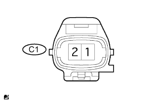
Disconnect the C1 sensor connector.
-
Measure the resistance of the sensor.
Standard resistance Tester Connection Sensor Condition Specified Condition 1 - 2 Cold 835 to 1,400 Ω 1 - 2 Hot 1,060 to 1,645 Ω Note
In the chart above, the terms "cold" and "hot" refer to the temperature of the sensor. "Cold" means approximately -10 to 50°C (14 to 122°F). "Hot" means approximately 50 to 100°C (122 to 212°F).
NG 
REPLACE CAMSHAFT POSITION SENSOR
OK 
-
-
CHECK WIRE HARNESS (CAMSHAFT POSITION SENSOR - ECM)
-
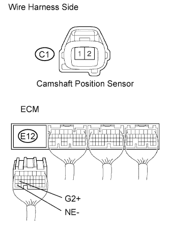
Disconnect the C1 sensor connector.
-
Disconnect the E12 ECM connector.
-
Measure the resistance of the wire harness side connectors.
Standard resistance Tester Connection Specified Condition C1-1 - E12-26 (G2+) Below 1 Ω C1-2 - E12-34 (NE-) Below 1 Ω C1-1 or E12-26 (G2+) - Body ground 10 kΩ or higher C1-2 or E12-34 (NE-) - Body ground 10 kΩ or higher
NG
REPAIR OR REPLACE HARNESS AND CONNECTOR
OK
-
-
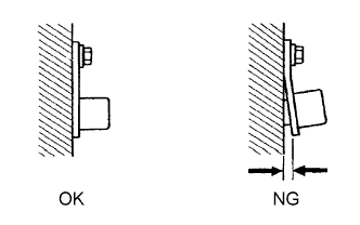
CHECK CAMSHAFT POSITION SENSOR (INSTALLATION)
-
Check that the sensor is installed correctly.
OK Sensor is installed correctly.
NG
SECURELY REINSTALL CAMSHAFT POSITION SENSOR
OK
-
-
CHECK CAMSHAFT
-
Check that the teeth of the camshaft do not have any cracks or deformation.
OK Teeth do not have cracks or deformation.
NG
REPLACE CAMSHAFT
OK 
REPLACE ECM
-