AUTOMATIC TRANSMISSION SYSTEM A/T P Indicator Circuit
DESCRIPTION
The propeller shaft and wheels are free even when the transmission shift lever is on P, as long as the transfer shift lever is on N. The A/T P indicator illuminates to warn the driver that the propeller shaft and wheels are not locked.
If the A/T P indicator illuminates, the transfer shift lever should be moved from N.
WIRING DIAGRAM
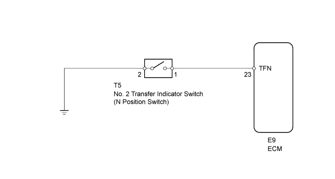
INSPECTION PROCEDURE
PROCEDURE
-
CHECK WIRE HARNESS (NO. 2 TRANSFER INDICATOR SWITCH - BODY GROUND)
-
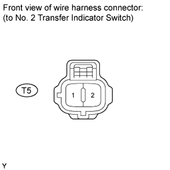
Disconnect the T5 switch connector.
-
Measure the resistance of the wire harness side connector.
Standard resistance Tester Connection Condition Specified Condition T5-2 - Body ground Always Below 1 Ω
NG 
REPAIR OR REPLACE HARNESS AND CONNECTOR
OK 
-
-
INSPECT NO. 2 TRANSFER INDICATOR SWITCH (TRANSFER NEUTRAL POSITION SWITCH)
-
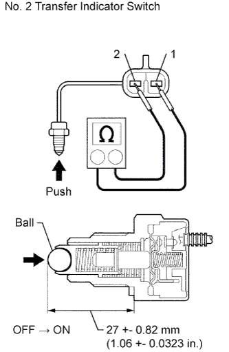
Remove the transfer indicator switch.
-
Measure the resistance of the switch when pushing the ball at the tip of the switch.
Standard resistance Tester Connection Switch Condition Specified Condition 1 - 2 Not pushed 10 kΩ or higher 1 - 2 Pushed Below 1 Ω
NG
REPLACE NO. 2 TRANSFER INDICATOR SWITCH
OK
-
-
CHECK WIRE HARNESS (NO. 2 TRANSFER INDICATOR SWITCH - ECM)
-
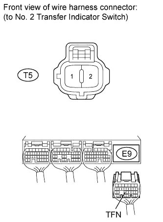
Disconnect the T5 switch connector.
-
Disconnect the E9 ECM connector.
-
Measure the resistance of the wire harness side connectors.
Standard resistance Tester Connection Condition Specified Condition E9-23 (TFN) - T5-1 Always Below 1 Ω E9-23 (TFN) or T5-1 - Body ground Always 10 kΩ or higher
NG
REPAIR OR REPLACE HARNESS AND CONNECTOR
OK 
REPLACE ECM
-