POWER STEERING SYSTEM TERMINALS OF ECU
CHECK POWER STEERING ECU
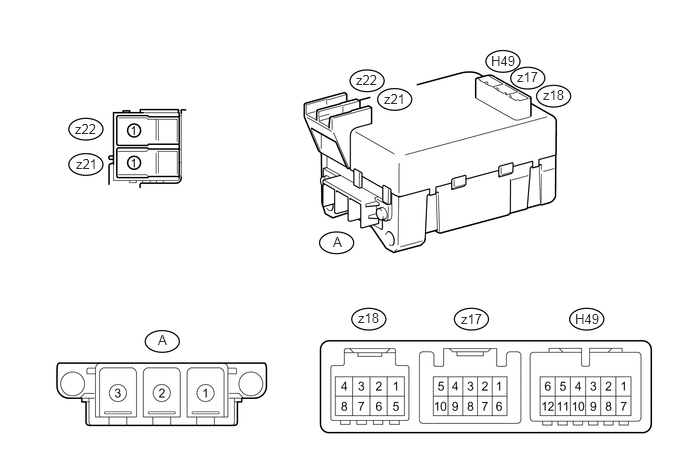 Tip:
Tip:As connector A is connected to the power steering motor with screws, the terminals cannot be checked while the connector is still connected to the power steering motor.
Terminal No. (Symbol)
Terminal Description
A-1 (PHC)
V phase motor output
A-2 (PHA)
U phase motor output
A-3 (PHB)
W phase motor output
Measure the voltage and resistance according to the value(s) in the table below.
Terminal No. (Symbol)
Wiring Color
Terminal Description
Condition
Specified Condition
H49-2 (CANH) - H49-8 (CANL)
SB - W
CAN communication line
Ignition switch off
54 to 69 Ω
H49-5 (IG) - Body ground
L - Body ground
IG power supply
Ignition switch ON
11 to 14 V
z17-3 (R1) - Body ground
W - Body ground
Rotation angle sensor excitation signal 1
Engine running, steering wheel being turned
4.5 to 8.5 V
z17-5 (R2) - Body ground
G - Body ground
Rotation angle sensor excitation signal 2
Engine running, steering wheel being turned
4.5 to 8.5 V
z17-6 (S4) - Body ground
L - Body ground
Rotation angle sensor COS aspect input signal
Engine running, steering wheel being turned
Below 1.5 V
z17-7 (S2) - Body ground
Y - Body ground
Rotation angle sensor COS aspect input signal
Engine running, steering wheel being turned
-2.0 to 2.0 V
z17-8 (S3) - Body ground
B - Body ground
Rotation angle sensor SIN aspect input signal
Engine running, steering wheel being turned
Below 1.5 V
z17-9 (S1) - Body ground
R - Body ground
Rotation angle sensor SIN aspect input signal
Engine running, steering wheel being turned
-2.0 to 2.0 V
z18-1 (TRQG) - Body ground
- (Not available) - Body ground
Torque sensor ground
Always
Below 1 Ω
z18-2 (TRQ2) - z18-1 (TRQG)
- (Not available)
Torque sensor signal 2
Engine running, steering wheel not turned (without load)
2.3 to 2.7 V
Engine running, steering wheel turned to right with vehicle stopped
0.95 to 2.5 V
Engine running, steering wheel turned to left with vehicle stopped
2.5 to 4.04 V
z18-3 (TRQV) - z18-1 (TRQG)
- (Not available)
Torque sensor power supply
Ignition switch ON
8.5 to 11 V
z18-5 (TRQF) - z18-1 (TRQG)
- (Not available)
Torque sensor reference voltage
Ignition switch ON
3.28 to 3.32 V
z18-7 (TRQ1) - z18-1 (TRQG)
- (Not available)
Torque sensor signal 1
Engine running, steering wheel not turned (without load)
2.3 to 2.7 V
Engine running, steering wheel turned to right with vehicle stopped
2.5 to 4.04 V
Engine running, steering wheel turned to left with vehicle stopped
0.95 to 2.5 V
z21-1 (PGND) - Body ground
B - Body ground
Power ground
Always
Below 1.5 V
z22-1 (PIG) - Body ground
R - Body ground
Motor power supply
Always
11 to 14 V
If the result is not as specified, the ECU may have a malfunction.