OIL PUMP REMOVAL
CAUTION / NOTICE / HINT
The necessary procedures (adjustment, calibration, initialization, or registration) that must be performed after parts are removed and installed, or replaced during timing chain cover sub-assembly removal/installation are shown below.
| Replaced Part or Performed Procedure | Necessary Procedure | Effect/Inoperative Function when Necessary Procedure not Performed | Link | |
|---|---|---|---|---|
| Battery terminal is disconnected/reconnected | Perform steering sensor zero point calibration | Lane departure alert system (w/ Steering Control) | ||
| Pre-collision system | ||||
| Memorize steering angle neutral point | Parking assist monitor system | |||
| Panoramic view monitor system | ||||
| Replacement of ECM | Vehicle Identification Number (VIN) registration | MIL comes on | ||
| Perform code registration (Immobiliser system) | Engine start function | See Service Bulletin for the registration method. | ||
|
Inspection after repair |
|
||
| Replacement of automatic transaxle assembly | Perform the following procedures in the order shown:
|
|
Click here for U761E Initialization Click here for U761E Registration |
|
| Replacement of ECM (If possible, read the transaxle compensation code from the previous ECM) |
Possible | Perform the following procedures in the order shown:
|
||
| Impossible | Perform the following procedures in the order shown:
|
|||
| Replacement of ECM | Perform code registration (Immobiliser function) |
|
See Service Bulletin for the registration method. | |
| Suspension, tires, etc.*1 | Rear television camera assembly optical axis (Back camera position setting) | Parking assist monitor system | Click here for Initialization Click here for Calibration |
|
|
Panoramic view monitor system | Click here for Initialization Click here for Calibration |
||
| Replacement of front bumper assembly | Front television camera view adjustment | |||
| Front wheel alignment adjustment | Perform system variant learning and acceleration sensor zero point calibration. |
|
||
PROCEDURE
-
INSTALL ENGINE ASSEMBLY TO ENGINE STAND
-
REMOVE IGNITION COIL ASSEMBLY
-
DISCONNECT NO. 2 VENTILATION HOSE
-
REMOVE FUEL PUMP PROTECTOR
-
DISCONNECT NO. 2 FUEL TUBE SUB-ASSEMBLY
-
REMOVE NO. 1 FUEL PIPE
-
REMOVE NO. 1 FUEL PIPE SUB-ASSEMBLY
-
REMOVE FUEL PUMP WITH SEAL SUB-ASSEMBLY
-
REMOVE EGR VALVE BRACKET
-
Remove the engine cover joint and separate the fuel hose bracket from the EGR valve bracket.
-
Remove the 4 bolts and 2 EGR valve brackets.
-
-
REMOVE CYLINDER HEAD COVER SUB-ASSEMBLY
-
REMOVE CRANKSHAFT POSITION SENSOR
-
REMOVE CRANKSHAFT PULLEY
-
REMOVE CAMSHAFT TIMING OIL CONTROL SOLENOID ASSEMBLY
-
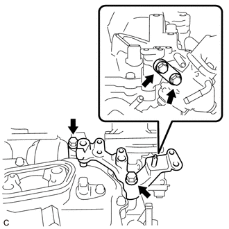
REMOVE V-RIBBED BELT TENSIONER ASSEMBLY
-
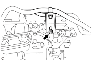
REMOVE ENGINE MOUNTING BRACKET RH
-
Remove the 4 bolts and engine mounting bracket RH.
-
-
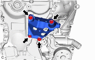
REMOVE TIMING CHAIN COVER SUB-ASSEMBLY
-
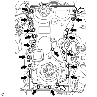

Bolt 
Nut Remove the 17 bolts and 2 nuts.
-
Remove the timing chain cover sub-assembly by prying between the timing chain cover sub-assembly and cylinder head sub-assembly, camshaft housing sub-assembly, cylinder block and stiffening crankcase assembly with a screwdriver as shown in the illustration.
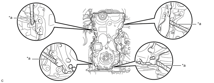
*a Protective Tape - - Note
Be careful not to damage the contact surfaces of the cylinder head sub-assembly, camshaft housing sub-assembly, cylinder block, stiffening crankcase assembly or timing chain cover sub-assembly.
Tech Tips
Tape the screwdriver tip before use.
-
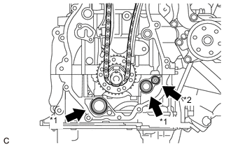
*1 Oil Pump Gasket *2 Oil Hole Cover Gasket Remove the 2 oil pump gaskets and oil hole cover gasket from the stiffening crankcase assembly.
-
-
REMOVE TIMING CHAIN COVER OIL SEAL
-
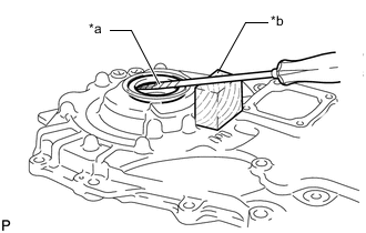
*a Protective Tape *b Wooden Block Using a screwdriver and wooden block, pry out the timing chain cover oil seal.
Note
Do not damage the surface of the timing chain cover oil seal press fit hole.
Tech Tips
Tape the screwdriver tip before use.
-