REAR STABILIZER BAR INSTALLATION
PROCEDURE
-
INSTALL REAR STABILIZER BUSHING (for LH Side)
-
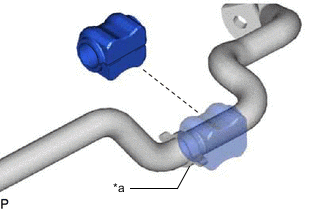
*a Bushing Stopper Install the rear stabilizer bushing to the rear stabilizer bar on the outside of the bush stoppers as shown in the illustration.
-
-
INSTALL REAR STABILIZER BUSHING (for RH Side)
Tech Tips
Use the same procedure described for the LH side.
-
INSTALL REAR STABILIZER BAR
-
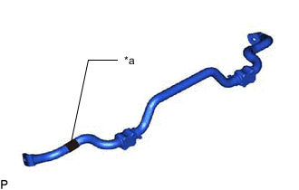
*a Paint Mark Install the rear stabilizer bar so that the paint mark is facing the right side of the vehicle.
-
-
INSTALL REAR NO. 1 STABILIZER BAR BRACKET (for LH Side)
-
Install the rear No. 1 stabilizer bar bracket to the rear suspension member with the 2 nuts.
- Torque:
- 60 N*m { 612 kgf*cm, 44 ft.*lbf }
-
-
INSTALL REAR NO. 1 STABILIZER BAR BRACKET (for RH Side)
Tech Tips
Use the same procedure described for the LH side.
-
INSTALL REAR UPPER COIL SPRING INSULATOR LH
-
INSTALL REAR LOWER COIL SPRING INSULATOR LH
-
INSTALL REAR COIL SPRING LH
-
INSTALL REAR SUSPENSION BRACE SUB-ASSEMBLY
-
Install the rear suspension brace sub-assembly to the rear suspension member with the 4 bolts.
- Torque:
- 35 N*m { 357 kgf*cm, 26 ft.*lbf }
-
-
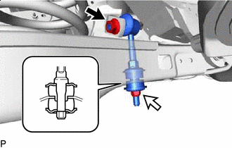
INSTALL REAR STABILIZER LINK ASSEMBLY LH
Note
Since the rear stabilizer link, rear stabilizer cushions and nut (B) are not reusable, new parts must be installed.
-

Nut (A) 
Nut (B) Install a new rear stabilizer link assembly LH and 2 new rear stabilizer cushions to the rear No. 2 suspension arm assembly with a new nut (B) as shown in the illustration.
- Torque:
- 30 N*m { 306 kgf*cm, 22 ft.*lbf }
Note
Be sure to install the rear stabilizer cushions in the correct direction as shown in the illustration.
-
Install the rear stabilizer link assembly LH to the rear stabilizer bar with the nut (A).
- Torque:
- 74 N*m { 755 kgf*cm, 55 ft.*lbf }
Tech Tips
If the ball joint turns together with the nut, use a 6 mm hexagon wrench to hold the stud.
-
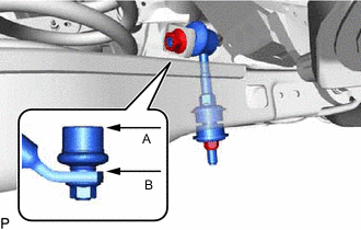
Adjust the rear stabilizer link assembly LH so that A and B are parallel as shown in the illustration.
-
-
INSTALL REAR STABILIZER LINK ASSEMBLY RH
Tech Tips
Use the same procedure described for the LH side.
-
STABILIZE SUSPENSION
-
TIGHTEN REAR NO. 2 SUSPENSION ARM ASSEMBLY LH
-
INSTALL REAR HEIGHT CONTROL SENSOR SUB-ASSEMBLY LH
-
INSTALL REAR SUSPENSION ARM COVER LH
-
INSTALL REAR WHEEL
-
INSPECT AND ADJUST REAR WHEEL ALIGNMENT
-
HEIGHT CONTROL SENSOR SIGNAL INITIALIZATION
-
PERFORM INITIALIZATION