VEHICLE STABILITY CONTROL SYSTEM, Diagnostic DTC:C1251
| DTC Code | DTC Name |
|---|---|
| C1251 | Open in Pump Motor Circuit |
DESCRIPTION
The motor relay (semiconductor relay) is built into the master cylinder solenoid and drives the pump motor based on a signal from the skid control ECU.
DTC No. |
Detection Item |
DTC Detection Condition |
Trouble Area |
|---|---|---|---|
C1251 |
Open in Pump Motor Circuit |
There is an open in the motor system circuit (motor input circuit). |
|
CAUTION / NOTICE / HINT
When replacing the master cylinder solenoid, perform calibration (Click here).
Remove the hydraulic brake booster assembly before the inspection (Click here).
PROCEDURE
CHECK CONNECTION OF PUMP MOTOR WIRE HARNESS
Remove the hydraulic brake booster assembly.
Check the tightening torque of the 2 screws which secure the wire harness connecting the master cylinder solenoid and brake booster with accumulator pump assembly.
OK
The harness is tightened to the specified torque.
Torque
2.9 N*m{ 30 kgf*cm , 26 in.*lbf }
Result
Result
OK
NG
NG RETIGHTEN SCREWS
CHECK RESISTANCE OF PUMP MOTOR WIRE HARNESS
Using a screwdriver, remove the 2 screws and pull out the wire harness from the master cylinder solenoid.
-
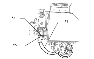
*1
Pump motor wire harness
*a
Red wire
*b
Black wire
Measure the resistance according to the value(s) in the table below.
Standard Resistance
Tester Connection
Condition
Specified Condition
Red wire terminal - Black wire terminal
Always
Below 2 Ω
Result
Result
OK
NG
RECONFIRM DTC
Reassemble the hydraulic brake booster assembly.
Install the hydraulic brake booster assembly.
Clear the DTCs.
Chassis > ABS/VSC/TRC > Clear DTCs
Check if the same DTC is output.
Result
Result
Proceed to
DTC is not output
A
DTC is output
B
Chassis > ABS/VSC/TRC > Trouble Codes