STARTING SYSTEM INSPECTION
-
INSPECT STARTER ASSEMBLY (for 2.0 kW Type)
Note
The following tests must be performed within 3 to 5 seconds to prevent the coil from burning out.
-
Perform the pull-in test.
-
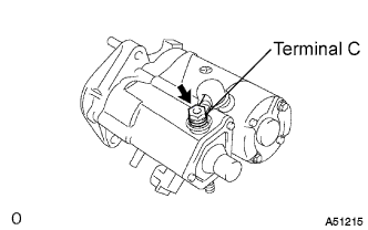
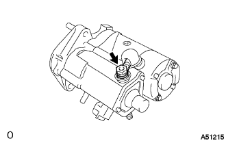
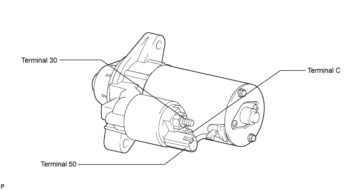
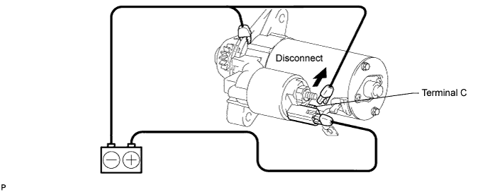
Disconnect the field coil lead wire from terminal C.
-
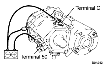
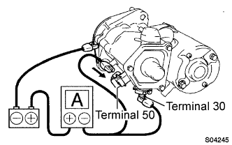
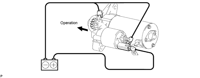
Connect the battery to the magnetic switch as shown in the illustration. Check that the clutch pinion gear is extended.
-
-
Perform the hold test.
-
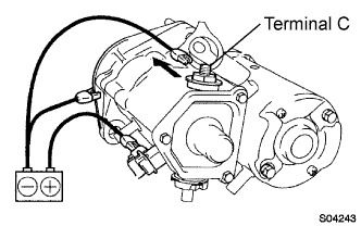
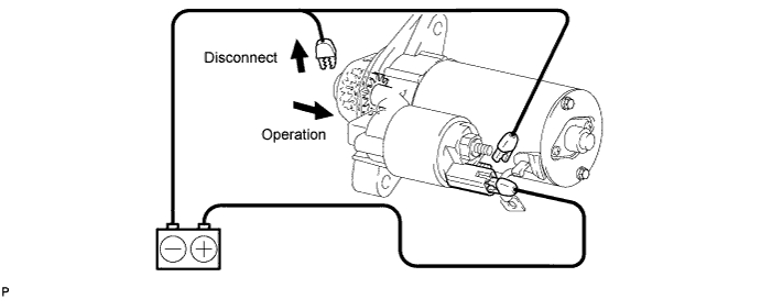
Disconnect the negative (-) lead from terminal C while sustaining the above condition (a). Check that the pinion gear remains extended.
-
-
Check the return operation.
-
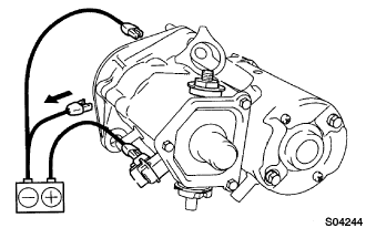
Disconnect the negative (-) lead from the starter body. Check that the clutch pinion gear returns inward.
-
-
Perform the operation test without any load.
-
Connect the field coil lead wire to terminal C.
- Torque:
- 5.9 N*m { 60 kgf*cm, 52 in.*lbf }
-
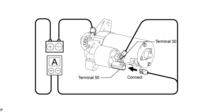
Clamp the starter in a vise.
-
Connect the battery and ammeter to the starter as shown in the illustration.
-
Check that the ammeter indicates the specified current.
Standard current 100 A or less at 11.5 V
-
-
-
INSPECT STARTER ASSEMBLY (for 2.2 kW Type)
Note
These tests must be performed within 3 to 5 seconds to prevent the coil from burning out.
-
Perform pull-in test.
-
Remove the nut, and then disconnect the field coil core from terminal C.
-
Connect the battery to the magnet starter switch as shown in the illustration. Then check that the clutch pinion gear moves outward.
If the clutch pinion gear does not move, replace the magnet starter switch assembly.
-
-
Perform holding test.
-
When the battery is connected as above with the clutch pinion gear out, disconnect the negative (-) lead from terminal C. Check that the pinion gear remains out.
If the clutch pinion gear returns inward, replace the magnet starter switch assembly.
-
-
Inspect clutch pinion gear return.
-
Disconnect the negative (-) lead from the starter body. Check that the clutch pinion gear returns inward.
If the clutch pinion gear does not return inward, replace the magnet starter switch assembly.
-
-
Perform operation test without load.
-
Connect the field coil lead wire to terminal C with the nut.
- Torque:
- 8.0 N*m { 82 kgf*cm, 71 in.*lbf }
-
Mount the starter in a vise between aluminum plates.
-
Connect the battery and ammeter to the starter as shown in the illustration.
-
Check that the starter rotates smoothly and steadily while the pinion gear is moving outward. Then measure the current.
Standard current 123 A or less at 11.5 V If the result is not as specified, replace the starter assembly.
-
-
-
INSPECT STARTER ASSEMBLY (for 2.7 kW Type)
Note
The following tests must be performed within 3 to 5 seconds to prevent the coil from burning out.
-
Perform the pull-in test.
-
Disconnect the field coil lead wire from terminal C.
-
Connect the battery to the magnetic switch as shown in the illustration. Check that the clutch pinion gear is extended.
-
-
Perform the hold test.
-
Disconnect the negative (-) lead from terminal C while sustaining the above condition (a). Check that the pinion gear remains extended.
-
-
Check the return operation.
-
Disconnect the negative (-) lead from the starter body. Check that the clutch pinion gear returns inward.
-
-
Perform the operation test without any load.
-
Connect the field coil lead wire to terminal C.
- Torque:
- 24 N*m { 245 kgf*cm, 18 ft.*lbf }
-
Clamp the starter in a vise.
-
Connect the battery and ammeter to the starter as shown in the illustration.
-
Check that the ammeter indicates the specified current.
Standard current 180 A or less at 11.5 V
-
-