FRONT SUSPENSION SYSTEM
-
CONSTRUCTION
-
Front Shock Absorber Assembly
-
Graceful riding comfort and a high degree of handling stability with a feeling of oneness with the vehicle help enhancing by the adoption of wide-bore pistons for the front shock absorber assembly.
-
Linear, highly responsive damping characteristics have been produced from the very-low-speed range through the pressure-reducing effect of a large-bore piston (front strut) and by layering several kinds of different-diameter leaf valves with clever piston shapes.
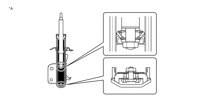
Text in Illustration *A For SHOWA Made - - -
Internal pressure fluctuations during the switch between pushing and pulling have been suppressed to the minimum and responsiveness has been further improved by layering different-diameter leaf valves on the piston's upper chamber side and sharing the damping force on the pushing side with the base valve side.
-
Linear, highly responsive damping from the very-low-speed range has produced linear handling and a sense of oneness with the vehicle.
-
High-dimensional handling stability can be achieved by combining the graceful ride achieved by a large piston bore and reducing internal pressure fluctuations.
-
A front shock absorber assembly made by SACHS was employed in accordance with specifications. High-dimensional handling stability and ride quality were both established in pursuit of damping.
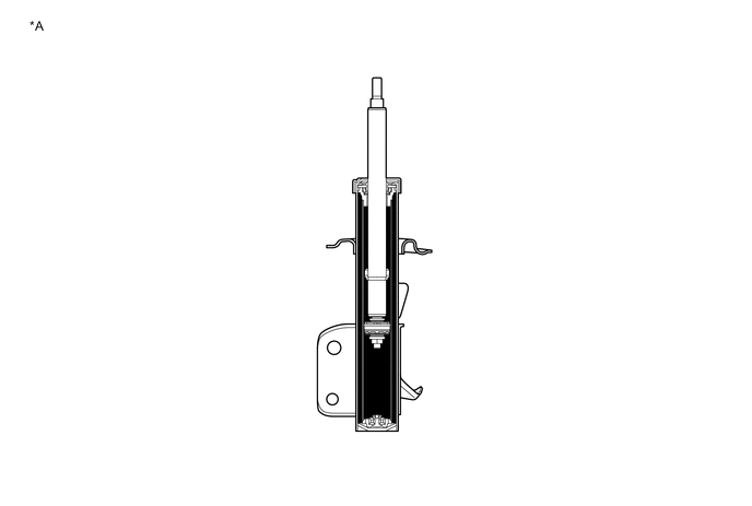
Text in Illustration *A For SACHS Made - -
-
-
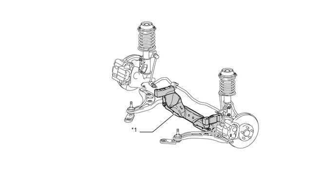
Front Lower Suspension Arm Sub-assembly
-
A lightweight single-plate structure along with high transverse rigidity and wide-ranging weight reductions have been achieved by a design and layout that overlaps the plane through which the ball center of the front lower ball joint assembly and the axis centers of the front/rear front-lower arm bush (three points) pass, with the plate-metal front lower suspension arm assembly.
-
Reductions of transmission of brake judder have progressed, and we have worked to achieve bush characteristics that balance stability and flutter at high dimensions.
-
Due to the special exhaust layout of the boxer engine, thermal insulation has been added on the exhaust side, and a heat-resistant rubber has been adopted for the lower arm bush out of concern for durability.
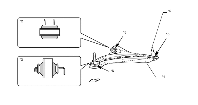
Text in Illustration *1 Front Lower Suspension Arm Assembly *2 Front Lower No. 2 Arm Bush (Cross Section) *3 Front Lower No. 1 Arm Bush (Cross Section) *4 Front Lower Ball Joint Assembly *5 Ball Center *6 Bush Axis Center 
Front - -
-
-
Front Stabilizer Bar
-
An 18.0-mm-diameter solid front stabilizer bar has been adopted. High roll rigidity has been enhanced through a more efficient layout; and stability at high dimensions, stability during braking, and emergency avoidance performance have been enhanced.
-
A ball-joint front stabilizer link assembly has been adopted. Responsiveness from the start of rolls has been heightened by attaching it to the front shock absorber assembly, and both maneuverability and stability have been achieved along with riding comfort by improving stabilizer effectiveness.
-
Self-lubricating rubber with excellent heat-resistance has been adopted for the stabilizer bar bush.
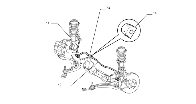
Text in Illustration *1 Front Stabilizer Link Assembly *2 Front Stabilizer Bar *3 Front No.1 Stabilizer Bar Bush - - *a Self Lubricating Rubber - -
-
-
Suspension Member
-
The vehicle mount parts have been changed to use a two-story structure that combines the pipes, and a closed cross section that matches the upper and lower suspension member (front crossmember sub-assembly) has been adopted as we continue to lower the location of the engine mount and adjust the boxer-engine-specific exhaust system with the aim of a lower center of gravity.
Text in Illustration *1 Suspension Member (Front Crossmember Sub-assembly) - - -
We are making the rack and pinion power steering gear assembly support more rigid and adopting a layout that ensures a long span with a pipe-shaped nut that passes through the member.
-
Total rigidity optimization (cross section tuning of the suspension member (front crossmember sub-assembly)) that includes the body has been carried out in order to help achieve a direct, crisp steering feel.
-
The position of the lower surface of the suspension member (front crossmember sub-assembly) has been lowered to the required ground height limit to lower the center of gravity.
-
-