CYLINDER BLOCK REASSEMBLY
PROCEDURE
INSTALL NO. 1 OIL NOZZLE SUB-ASSEMBLY
-
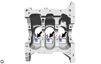
Using a 5 mm hexagon socket wrench, install the 3 No. 1 oil nozzle sub-assemblies with the 3 bolts.
10 N*m
102 kgf*cm
7 ft.*lbf
-
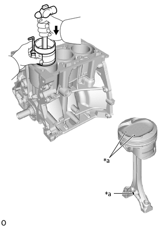
INSTALL PISTON (w/ Pin)
Note:If the piston pin is removed from the piston, replace the piston, piston pin and connecting rod sub-assembly with new ones.
Gradually heat the piston to 80 to 90°C (176 to 194°F).
Apply engine oil to the small end of a new connecting rod sub-assembly and a new piston pin.
-
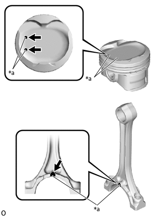
*a
Front Mark
Align the front marks of the piston and connecting rod sub-assembly and insert the connecting rod sub-assembly into the piston.
Using SST and a press, install the piston pin.
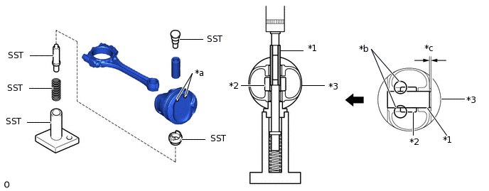
*1
Piston Pin
*2
Connecting Rod Sub-assembly
*3
Piston
-
-
*a
Front Mark
*b
Press
*c
1.2 to 2.4 mm (0.0472 to 0.0945 in.)
-
-

Rear Side
-
-
09221-25026
09221-00021
09221-00030
09221-00130
09221-00141
09221-00150
Note:Press in the piston pin from the front mark side of the piston.
Do not press in the piston pin at an angle.
Hold the connecting rod sub-assembly and check that the piston moves smoothly.
INSTALL PISTON RING SET
-
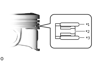
*1
Upper Side Rail
*2
Expander Spacer
*3
Lower Side Rail
Install the expander spacer and 2 side rails by hand.
-
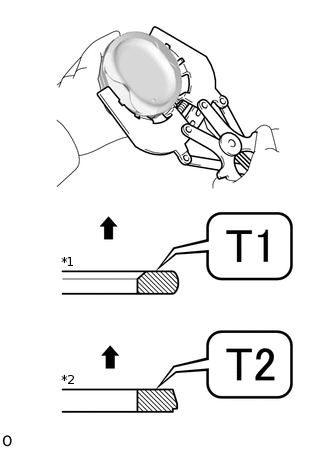
*1
No. 1 Compression Ring
*2
No. 2 Compression Ring
Upward
Using a piston ring expander, install the No. 1 compression ring and No. 2 compression ring as shown in the illustration.
Note:Install the No. 2 compression ring with the cutout facing downward.
-
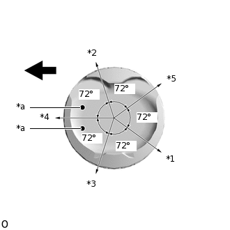
*1
No. 1 Compression Ring
*2
No. 2 Compression Ring
*3
Upper Side Rail
*4
Expander Spacer
*5
Lower Side Rail
*a
Front Mark
Engine Front
Position the piston ring set so that the ring ends are as shown in the illustration.
Note:Do not align the ring ends.
-
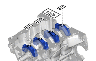
INSTALL CRANKSHAFT BEARING
Clean the main journals and both surfaces of the crankshaft bearings.
Install the 4 crankshaft bearings to the cylinder block sub-assembly as shown in the illustration.
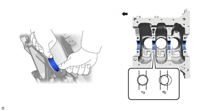
*a
Correct
*b
Incorrect
Engine Front
-
-
Note:Do not apply engine oil to the crankshaft bearings or the contact surfaces.
Both sides of the oil groove in the cylinder block sub-assembly should be visible through the oil feed holes in the crankshaft bearing. The amount visible on each side of the holes should be equal.
Do not allow coolant to come into contact with the crankshaft bearing inner surface.
If any coolant comes into contact with the crankshaft bearing inner surface, replace the crankshaft bearing with a new one.
Install the 4 crankshaft bearings.
-
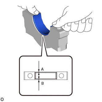
Install the crankshaft bearings to the crankshaft bearing caps.
Using a vernier caliper, measure the distance between the crankshaft bearing cap edge and the crankshaft bearing edge.
Difference Between (A) and (B)
0.8 mm (0.0315 in.) or less
Note:Do not apply engine oil to the crankshaft bearings or the contact surfaces.
-
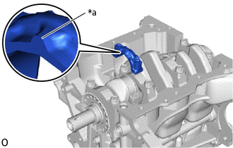
INSTALL CRANKSHAFT THRUST WASHER UPPER
-
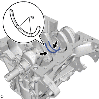
*a
Oil Groove
Install the 2 crankshaft thrust washer uppers to the No. 3 journal position of the cylinder block sub-assembly with the oil grooves facing outward.
Apply engine oil to the crankshaft thrust washer uppers.
-
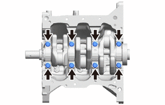
INSTALL CRANKSHAFT
Apply engine oil to the crankshaft bearings, then place the crankshaft on the cylinder block sub-assembly.
Apply engine oil to the crankshaft bearings.
-
Examine the number marks and install the crankshaft bearing caps to the cylinder block sub-assembly.
Apply a light coat of engine oil to the threads and under the heads of the crankshaft bearing cap set bolts.
-
Temporarily install the 8 crankshaft bearing cap set bolts.
-
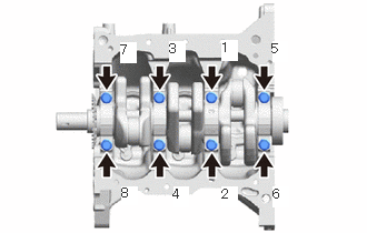
Uniformly tighten the 8 crankshaft bearing cap set bolts in the order shown in the illustration.
59 N*m
602 kgf*cm
44 ft.*lbf
Check that the crankshaft turns smoothly.
INSTALL CONNECTING ROD BEARING
-
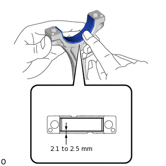
Install the connecting rod bearings to the connecting rod sub-assemblies and connecting rod bearing caps.
Using a vernier caliper, measure the distance between the edges of the connecting rod sub-assemblies and connecting rod bearings, and the connecting rod bearing caps and the connecting rod bearings.
Standard Dimension
2.1 to 2.5 mm (0.0827 to 0.0984 in.)
Note:Do not apply engine oil to the connecting rod bearings or the contact surfaces.
-
INSTALL PISTON SUB-ASSEMBLY WITH CONNECTING ROD
Apply engine oil to the cylinder walls, pistons, and surfaces of the connecting rod bearings.
-
*1
No. 1 Compression Ring
*2
No. 2 Compression Ring
*3
Upper Side Rail
*4
Expander Spacer
*5
Lower Side Rail
*a
Front Mark
Engine Front
Position the piston ring set so that the ring ends are as shown in the illustration.
Note:Do not align the ring ends.
-
*a
Front Mark
Using a piston ring compressor, push the correctly numbered piston sub-assembly and connecting rod sub-assembly into the cylinder with the front marks of the piston facing forward.
Note:When inserting the piston sub-assembly with connecting rod sub-assembly, do not allow it to make contact with the No. 1 oil nozzle sub-assembly.
Match the numbered connecting rod bearing cap with the connecting rod sub-assembly.
-
*a
Front Mark
Check that the front mark of the connecting rod bearing cap is facing in the correct direction and install the connecting rod bearing cap.
Apply a light coat of engine oil to the threads and under the heads of the connecting rod bolts.
Install the connecting rod bolts.
Note:The connecting rod bolts are tightened in 2 progressive steps.
Step 1:
-
Using SST, alternately tighten the connecting rod bolts of the connecting rod cap in several steps.
09205-16011
15 N*m
153 kgf*cm
11 ft.*lbf
-
Step 2:
-
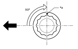
*a
Paint Mark
Engine Front
Mark the front of the connecting rod bolts with paint.
Further tighten the connecting rod bolts 90° as shown in the illustration.
-
Check that the paint marks are now at a 90° angle to the front.
Check that the crankshaft turns smoothly.
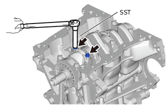
INSTALL OIL JET
-
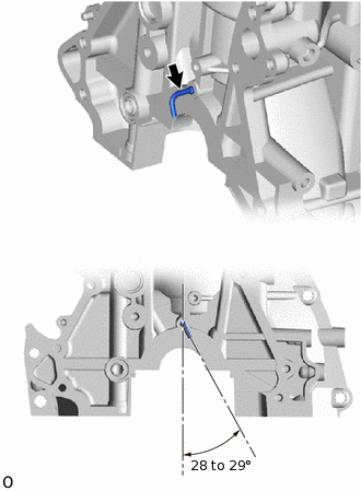
Install the oil jet to the cylinder block sub-assembly as shown in the illustration.
Note:Do not tap the tip of the oil jet.
-