AUTOMATIC TRANSMISSION SYSTEM (for 2KD-FTV) ECU Power Source Circuit
DESCRIPTION
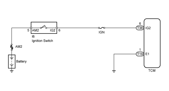
When the ignition switch is turned to ON, battery voltage is applied to terminal IG2 of the TCM.
WIRING DIAGRAM
INSPECTION PROCEDURE
Note
Inspect the fuses for circuits related to this system before performing the following inspection procedure.
PROCEDURE
-
INSPECT IGNITION SWITCH
-
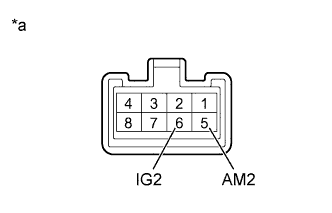
Text in Illustration *a Component without harness connected
(Ignition switch)
Disconnect the ignition switch connector.
-
Measure the resistance according to the value(s) in the table below.
Standard Resistance Tester Connection Switch Condition Specified Condition 5 (AM2) - 6 (IG2) LOCK 10 kΩ or higher 5 (AM2) - 6 (IG2) ON Below 1 Ω
NG 
REPLACE IGNITION SWITCH
OK 
-
-
CHECK HARNESS AND CONNECTOR (TCM - BODY GROUND)
-
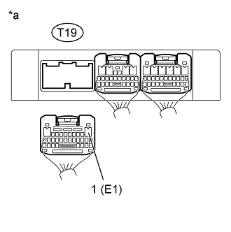
Text in Illustration *a Rear view of wire harness connector
(to TCM)
Disconnect the TCM connector.
-
Measure the resistance according to the value(s) in the table below.
Standard Resistance Tester Connection Condition Specified Condition T19-1 (E1) - Body ground Always Below 1 Ω
NG
REPAIR OR REPLACE HARNESS OR CONNECTOR
OK
-
-
CHECK TCM (TCM - BATTERY)
-
Turn the ignition switch to ON.
-
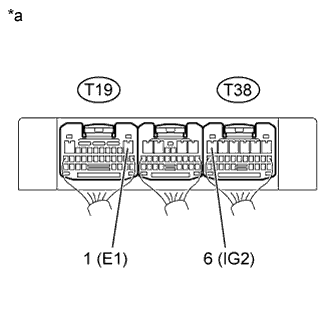
Text in Illustration *a Component with harness connected
(TCM)
Measure the voltage according to the value(s) in the table below.
Standard Voltage Tester Connection Switch Condition Specified Condition T38-6 (IG2) - T19-1 (E1) Ignition switch ON 11 to 14 V
NG
REPAIR OR REPLACE HARNESS OR CONNECTOR
OK 
REPLACE TCM
-