GLOW PLUG INSTALLATION
PROCEDURE
-
INSTALL GLOW PLUG ASSEMBLY
-
Using a 12 mm deep socket wrench, install the 4 glow plug assemblies.
- Torque:
- 13 N*m { 133 kgf*cm, 10 ft.*lbf }
-
-
INSTALL NO. 1 GLOW PLUG CONNECTOR
-
Install the No. 1 glow plug resistor insulator.
-
Install the No. 1 glow plug connector by uniformly tightening the 4 nuts.
- Torque:
- 1.0 N*m { 10 kgf*cm, 9 in.*lbf }
-
Install the 4 screw grommets.
-
Connect the engine wire and install the No. 2 glow plug resistor insulator and plate washer with the nut.
- Torque:
- 5.0 N*m { 51 kgf*cm, 44 in.*lbf }
-
-
INSTALL INTAKE PIPE
-
Temporarily install the intake pipe.
-
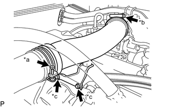
*a Hose Clamp A *b Hose Clamp B *c Bolt Install the 2 bolts.
- Torque:
- 18 N*m { 184 kgf*cm, 13 ft.*lbf }
-
Tighten the 2 hose clamps to secure the intake pipe.
- Torque:
- for hose clamp A
- 4.0 N*m { 41 kgf*cm, 35 in.*lbf }
- for hose clamp B
- 6.0 N*m { 61 kgf*cm, 53 in.*lbf }
-
-
CONNECT CABLE TO NEGATIVE BATTERY TERMINAL
Note
When disconnecting the cable, some systems need to be initialized after the cable is reconnected.