ЗАДНИЙ САЛЬНИК КОЛЕНЧАТОГО ВАЛА УСТАНОВКА

-
INSTALL ENGINE REAR OIL SEAL
-
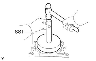
Using SST and a hammer, tap in a new oil seal.
- SST
- 09518-36030
- 09950-70010 ( 09951-07200 )
Acceptable depth from the top flat face of the oil seal retainer 0 to 0.5 mm (0 to 0.020 in.) Note
Be sure to make the oil seal horizontal when embedded.
-
Apply a bit of MP grease to the oil seal's lip.
Note
Keep the lip clean. Do not bring dirt or dusts on that area.
-
-
INSTALL ENGINE REAR OIL SEAL RETAINER
-
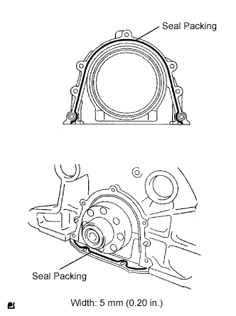
Remove oil seal packing (FIPG) from oil pan and cylinder block.
-
Apply a seal packing to the specific places described in the illustration.
Seal packing Toyota Genuine Seal Packing Black, Three Bond 1207B or equivalent Note
-
After applying FIPG install the engine rear oil seal retainer within 3 minutes and then tighten its bolts within 15 minutes.
-
Do not start the engine 2 hours after the installation.
-
-
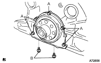
Install the engine rear oil seal retainer with the 7 bolts.
- Torque:
- Bolt A
- 13 N*m { 133 kgf*cm, 10 ft.*lbf }
- Bolt B
- 16 N*m { 166 kgf*cm, 12 ft.*lbf }
-
-
INSTALL REAR END PLATE
-
Установите заднюю крышку и закрепите ее болтом.
- Torque:
- 8,0 Н*м { 82 кгс*см, 71 фунт-сила-дюйм }
-
-
INSTALL FLYWHEEL SUB-ASSEMBLY
-
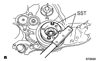
С помощью SST зафиксируйте коленчатый вал.
- SST
- 09213-58013
- 09330-00021
-
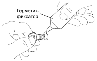
Нанесите герметик на два или три витка резьбы 8 болтов.
Герметик Фирменный герметик 1344 от компании Toyota, Three Bond 1344 или аналогичный -
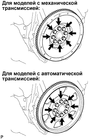
Для моделей с механической трансмиссией
-
Установите маховик и закрепите его 8 болтами.
- Torque:
- 178 Н*м { 1 815 кгс*см, 131 фунт-сила-фут }
-
-
Для моделей с автоматической трансмиссией.
-
Установите маховик, ведущий диск и заднюю распорную втулку ведущего диска и закрепите их 8 болтами.
- Torque:
- 178 Н*м { 1 815 кгс*см, 131 фунт-сила-фут }
-
-
-
INSTALL CLUTCH DISC ASSEMBLY (for Manual Transmission)
-
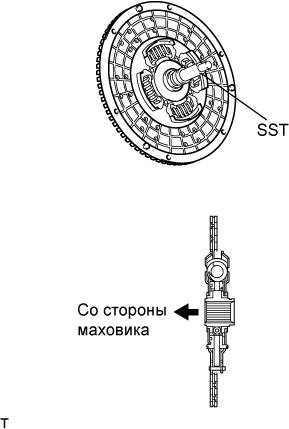
Insert SST into the clutch disc assembly, then insert them into the flywheel sub-assembly.
- SST
- 09301-00110
Note
Take care not to insert the clutch disc assembly in the wrong direction.
-
-
INSTALL CLUTCH COVER ASSEMBLY (for Manual Transmission)
-
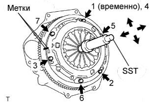
Align the matchmarks on the clutch cover assembly with the one on the flywheel sub-assembly.
-
Following the procedures shown in the illustration, tighten the 6 bolts starting from the bolt located near the knock pin on the top.
- SST
- 09301-00110
- Torque:
- 19 N*m { 195 kgf*cm, 14 ft.*lbf }
Tech Tips
-
Evenly tighten the bolts by following the order shown in the illustration.
-
Tighten the bolts after checking that the disc is in the center by lightly moving the SST up and down, left and right.
-
-
INSPECT AND ADJUST CLUTCH COVER ASSEMBLY (for Manual Transmission)
-
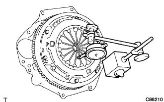
Using a dial indicator with a roller instrument, check the diaphragm spring tip alignment.
Maximum non-alignment 1.3 mm (0.051 in.) -
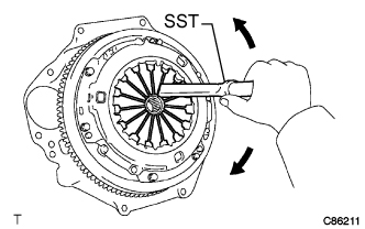
If alignment is not as specified, adjust the diaphragm spring tip alignment using SST.
- SST
- 09333-00013
-
-
INSTALL AUTOMATIC TRANSMISSION ASSEMBLY (for Automatic Transmission)
-
INSTALL MANUAL TRANSMISSION UNIT ASSEMBLY (for Manual Transmission)