WIRELESS DOOR LOCK CONTROL SYSTEM(w/ Entry and Start System) TERMINALS OF ECU
CHECK MAIN BODY ECU (INSTRUMENT PANEL JUNCTION BLOCK ASSEMBLY)
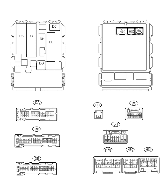
Disconnect the H79, H80, DB, DE and DG ECU connectors.
Measure the voltage and resistance according to the value(s) in the table below.
Terminal No. (Symbol)
Wiring Color
Terminal Description
Condition
Specified Condition
H79-4 (BATB) - Body ground
BR - Body ground
Battery power supply
Always
11 to 14 V
DG-1 (ALTB) - Body ground
W - Body ground
Battery power supply
Always
11 to 14 V
DB-30 (BECU) - Body ground
W - Body ground
Power supply
Always
11 to 14 V
DE-28 (GND1) - Body ground
W-B - Body ground
Ground
Always
Below 1 Ω
H80-4 (GND2) - Body ground
W-B - Body ground
Ground
Always
Below 1 Ω
If the result is not as specified, there may be a malfunction on the wire harness side.
Reconnect the H79, H80, DB, DE and DG ECU connectors.
Measure the voltage according to the value(s) in the table below.
Table 1. for LHD Terminal No. (Symbol)
Wiring Color
Terminal Description
Condition
Specified Condition
DA-21 (DCTY) - Body ground
W - Body ground
Front door courtesy light switch LH input
Driver side door open
Below 1 V
Driver side door close
11 to 14 V
DE-20 (PCTY) - Body ground
BR - Body ground
Front door courtesy light switch RH input
Front passenger side door open
Below 1 V
Front passenger side door closed
11 to 14 V
H79-8 (LCTY) - Body ground
SB - Body ground
Rear door courtesy light switch LH input
Rear door LH open
Below 1 V
Rear door LH closed
11 to 14 V
DE-19 (RCTY) - Body ground
LG - Body ground
Rear door courtesy light switch RH input
Rear door RH open
Below 1 V
Rear door RH closed
11 to 14 V
DA-7 (BCTY) - Body ground
LG - Body ground
Back door courtesy light switch input
Back door open
Below 1 V
Back door closed
11 to 14 V
H79-25 (LSWD) - Body ground
Y - Body ground
Front door lock position switch LH input
Driver side door unlocked
Below 1 V
Engine switch off, all doors closed and driver side door locked
Pulse generation
(see waveform 1 or 2)
H79-10 (LSWP) - Body ground
LG - Body ground
Front door lock position switch RH input
Front passenger side door unlocked
Below 1 V
Engine switch off, all doors closed and passenger side door locked
Pulse generation
(see waveform 3 or 4)
H81-10 (LSR) - Body ground
Y - Body ground
Rear door lock position switch input
Rear door unlocked
Below 1 V
Engine switch off, all doors closed and rear door locked
Pulse generation
(see waveform 5 or 6)
H81-2 (BZR) - Body ground
L - Body ground
Wireless door lock buzzer signal
Wireless door lock buzzer off
Below 1 V
Wireless door lock buzzer on
Pulse generation
Table 2. for RHD Terminal No. (Symbol)
Wiring Color
Terminal Description
Condition
Specified Condition
DC-6 (DCTY) - Body ground
BR - Body ground
Front door courtesy light switch RH input
Driver side door open
Below 1 V
Driver side door closed
11 to 14 V
DA-24 (PCTY) - Body ground
W - Body ground
Front door courtesy light switch LH input
Front passenger side door open
Below 1 V
Front passenger side door closed
11 to 14 V
H79-8 (LCTY) - Body ground
SB - Body ground
Rear door courtesy light switch LH input
Rear door LH open
Below 1 V
Rear door LH closed
11 to 14 V
DE-19 (RCTY) - Body ground
LG - Body ground
Rear door courtesy light switch RH input
Rear door RH open
Below 1 V
Rear door RH closed
11 to 14 V
DA-7 (BCTY) - Body ground
LG - Body ground
Back door courtesy light switch input
Back door open
Below 1 V
Back door closed
11 to 14 V
H79-25 (LSWD) - Body ground
LG - Body ground
Front door lock position switch RH input
Driver side door unlocked
Below 1 V
Engine switch off, all doors closed and driver side door locked
Pulse generation
(see waveform 1 or 2)
H79-10 (LSWP) - Body ground
LG - Body ground
Front door lock position switch LH input
Front passenger side door unlocked
Below 1 V
Engine switch off, all doors closed and passenger side door locked
Pulse generation
(see waveform 3 or 4)
H81-10 (LSR) - Body ground
Y - Body ground
Rear door lock position switch input
Rear door unlocked
Below 1 V
Engine switch off, all doors closed and rear door locked
Pulse generation
(see waveform 5 or 6)
H81-2 (BZR) - Body ground
L - Body ground
Wireless door lock buzzer signal
Wireless door lock buzzer off
Below 1 V
Wireless door lock buzzer on
Pulse generation
If the result is not as specified, the ECU may have a malfunction.
-
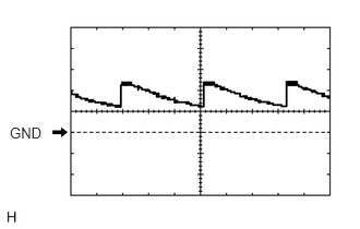
Using an oscilloscope, check waveform 1.
Table 3. Waveform 1 (Reference) Item
Content
Terminal No. (Symbol)
H79-25 (LSWD) - Body ground
Tool Setting
5 V/DIV., 20 ms/DIV.
Condition
Engine switch off, all doors closed and driver side door locked
-
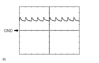
Using an oscilloscope, check waveform 2.
Table 4. Waveform 2 (Reference) Item
Content
Terminal No. (Symbol)
H79-25 (LSWD) - Body ground
Tool Setting
5 V/DIV., 20 ms/DIV.
Condition
Engine switch off, all doors closed and driver side door locked
-
Using an oscilloscope, check waveform 3.
Table 5. Waveform 3 (Reference) Item
Content
Terminal No. (Symbol)
H79-10 (LSWP) - Body ground
Tool Setting
5 V/DIV., 20 ms/DIV.
Condition
Engine switch off, all doors closed and passenger side door locked
-
Using an oscilloscope, check waveform 4.
Table 6. Waveform 4 (Reference) Item
Content
Terminal No. (Symbol)
H79-10 (LSWP) - Body ground
Tool Setting
5 V/DIV., 20 ms/DIV.
Condition
Engine switch off, all doors closed and passenger side door locked
-
Using an oscilloscope, check waveform 5.
Table 7. Waveform 5 (Reference) Item
Content
Terminal No. (Symbol)
H81-10 (LSR) - Body ground
Tool Setting
5 V/DIV., 20 ms/DIV.
Condition
Engine switch off, all doors closed and rear door locked
-
Using an oscilloscope, check waveform 6.
Table 8. Waveform 6 (Reference) Item
Content
Terminal No. (Symbol)
H81-10 (LSR) - Body ground
Tool Setting
5 V/DIV., 20 ms/DIV.
Condition
Engine switch off, all doors closed and rear door locked
CHECK CERTIFICATION ECU
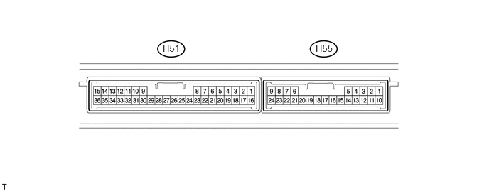
Disconnect the H51 ECU connector.
Measure the voltage and resistance according to the value(s) in the table below.
Terminal No. (Symbol)
Wiring Color
Terminal Description
Condition
Specified Condition
H51-1 (+B) - H51-15 (E)
W - W-B
+B power supply
Always
11 to 14 V
H51-15 (E) - Body ground
W-B - Body ground
Ground
Always
Below 1 Ω
H51-16 (IG) - H51-15 (E)
L - W-B
IG power supply
Engine switch off → Engine switch on (IG)
Below 1 V → 11 to 14 V
H51-17 (CUTB) - H51-15 (E)
W - W-B
+B power supply
Always
11 to 14 V
If the result is not as specified, there may be a malfunction in the wire harness.
Reconnect the H51 ECU connector.
Measure the voltage according to the value(s) in the table below.
Terminal No. (Symbol)
Wiring Color
Terminal Description
Condition
Specified Condition
H55-5 (RCO) - H51-15 (E)
V - W-B
Door control receiver power source
Engine switch off, all doors closed and transmitter switch not pressed → pressed
Below 1 V → 4.5 to 5.5 V
H55-15 (RDA) - H51-15 (E)
Y - W-B
Door control receiver data input signal
Engine switch off
11 to 14 V pulse generation at regular intervals
H55-16 (RSSI) - H51-15 (E)
L - W-B
Door control receiver electric wave existence signal
All doors locked, all doors closed and transmitter switch not pressed → pressed
11 to 14 V → Below 2 V
If the result is not as specified, the certification ECU may have a malfunction.