SUB BATTERY SYSTEM, Diagnostic DTC:B2304
| DTC Code | DTC Name |
|---|---|
| B2304 | Communication Error from Backup Relay (BURDIAG2) to Sub Battery Module |
DESCRIPTION
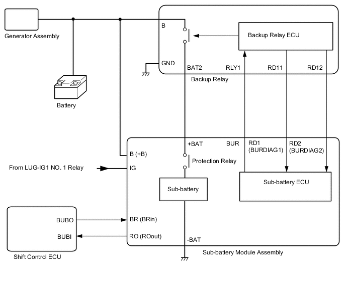
The sub-battery module assembly receives RD12 signals from the backup relay.
RD12 signals are PWM communication (Pulse Width Modulation: Modulates pulse width according to duty ratio) and indicates the normal/malfunction condition of the backup relay.
| DTC No. | Detection Item | DTC Detection Condition | Trouble Area | Warning Indicate | Memory |
|---|---|---|---|---|---|
| B2304 | Communication Error from Backup Relay (BURDIAG2) to Sub Battery Module | This DTC is stored when a malfunction is detected in communication from the backup relay (RD12) to the sub-battery module assembly continuously for 10 seconds. (3 trip detection logic) |
|
Comes on | DTC stored |
Tech Tips
The details of a DTC can be checked by using the DTC Sub Code of the freeze frame data that was recorded when the DTC was output.
| DTC Sub Code | Detail |
|---|---|
| "3E" | Open or short to +B in backup relay signal line (RD12) |
| "3F" | Short to ground in backup relay signal line (RD12) |
| "40" | Waveform malfunction in backup relay signal line (RD12) |
WIRING DIAGRAM
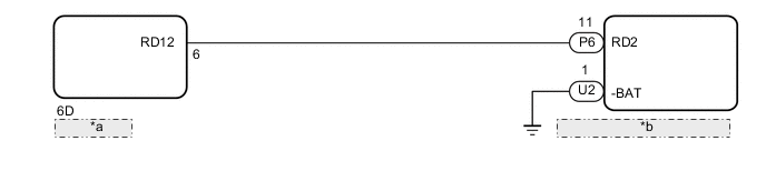
| *a | Backup Relay |
| *b | Sub-battery Module Assembly |
CONFIRMATION DRIVING PATTERN
-
Connect the GTS to the DLC3.
-
Turn the engine switch on (IG) and turn the GTS on.
-
Clear the DTCs.
-
Turn the engine switch off and wait for at least 30 seconds.
-
Turn the engine switch on (IG) and wait for at least 15 seconds or more. (A)
-
Turn the engine switch off and wait for at least 30 seconds. (B)
-
Repeat steps (A) through (B) shown above at least 3 times.
-
Turn the engine switch on (IG).
-
Turn the GTS on.
-
Enter the following menus: Body Electrical / Sub Battery Module / Trouble Codes.
-
Check the DTC.
Tech Tips
If a DTC is output, the system is malfunctioning.
CAUTION / NOTICE / HINT
Tech Tips
Read freeze frame data using the GTS. Freeze frame data records the sub battery module condition when malfunctions are detected.
PROCEDURE
-
CHECK CONNECTOR CONNECTION CONDITION (SUB-BATTERY MODULE ASSEMBLY)
-
Refer to the following procedures for removing the connector cover from the luggage compartment mat sub-assembly.
-
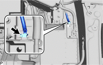
Check the connection condition of the sub-battery module assembly connector and the contact pressure of the terminal. Check the terminal for deformation, and check the connector for water ingress and foreign matter.
OK - The connector is connected securely. - The terminals are not deformed and are connected securely. - No water or foreign matter in each connector. Result Result Proceed to OK A NG (The connector is not connected securely.) B NG (The terminals are not making secure contact or are deformed, or water or foreign matter exists in a connector.) C
B 
CONNECT SECURELY
C
REPAIR OR REPLACE HARNESS OR CONNECTOR
A 
-
-
CHECK CONNECTOR CONNECTION CONDITION (BACKUP RELAY)
-
Refer to the following procedures for removing the backup relay from the luggage compartment mat sub-assembly.
-
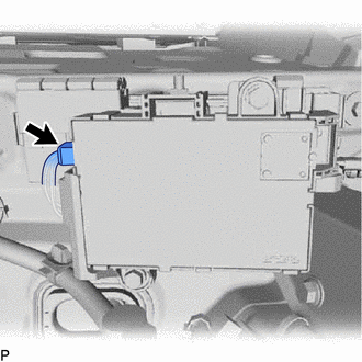
Check the connection condition of the backup relay connector and the contact pressure of the terminal. Check the terminal for deformation, and check the connector for water ingress and foreign matter.
OK - The connector is connected securely. - The terminals are not deformed and are connected securely. - No water or foreign matter in each connector. Result Result Proceed to OK A NG (The connector is not connected securely.) B NG (The terminals are not making secure contact or are deformed, or water or foreign matter exists in a connector.) C
B
CONNECT SECURELY
C
REPAIR OR REPLACE HARNESS OR CONNECTOR
A
-
-
CHECK DTC OUTPUT
-
Connect the GTS to the DLC3.
-
Turn the engine switch on (IG).
-
Turn the GTS on.
-
Clear the DTCs.
Body Electrical > Sub Battery Module > Clear DTCs -
Turn the engine switch off and wait for at least 30 seconds.
-
Turn the engine switch on (IG) and wait for at least 15 seconds or more. (A)
-
Turn the engine switch off and wait for at least 30 seconds. (B)
-
Repeat steps (A) through (B) shown above at least 3 times.
-
Turn the engine switch on (IG).
-
Turn the GTS on.
-
Enter the following menus: Body Electrical / Sub Battery Module / Trouble Codes.
Body Electrical > Sub Battery Module > Trouble Codes -
Read the DTCs.
Result Result Proceed to DTC B2304 is output A DTC is not output B
B
END
A
-
-
CHECK FREEZE FRAME DATA (DTC SUB CODE)
-
Check the DTC sub code displayed in the freeze frame data.
Result Result Proceed to "3E" is output A "3F" is output B "40" is output C
B 
INSPECT SUB-BATTERY MODULE ASSEMBLY Click here
C
CHECK HARNESS AND CONNECTOR (SUB-BATTERY MODULE ASSEMBLY - BACKUP RELAY) Click here
A
-
-
CHECK HARNESS AND CONNECTOR (SUB-BATTERY MODULE ASSEMBLY - BACKUP RELAY)
-
Disconnect the sub-battery module assembly connector.
-
Disconnect the backup relay connector.
-
Measure the resistance according to the value(s) in the table below.
Standard Resistance Tester Connection Condition Specified Condition P6-11 (RD2) - 6D-6 (RD12) Always Below 1 Ω P6-11 (RD2) or 6D-6 (RD12) - Other terminals Always 10 kΩ or higher -
Reconnect the sub-battery module assembly connector.
-
Reconnect the backup relay connector.
Result Proceed to OK NG
NG
REPAIR OR REPLACE HARNESS OR CONNECTOR
OK
-
-
INSPECT BACKUP RELAY
-
Disconnect the sub-battery module assembly connector
-
Turn the engine switch on (IG).
-
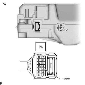
*a Rear view of wire harness connector
(to Sub-battery Module Assembly)
Measure the voltage according to the value(s) in the table below.
Standard Voltage Tester Connection Condition Specified Condition P6-11 (RD2) - Body ground Engine switch on (IG) 0 to 1 V Result Proceed to OK NG
OK
REPLACE SUB-BATTERY MODULE ASSEMBLY Click here
NG
REPLACE BACKUP RELAY Click here
-
-
INSPECT SUB-BATTERY MODULE ASSEMBLY
-
Disconnect the backup relay connector
-
Turn the engine switch on (IG).
-
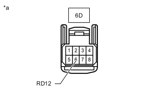
*a Front view of wire harness connector
(to Backup Relay)
Measure the voltage according to the value(s) in the table below.
Standard Voltage Tester Connection Condition Specified Condition 6D-6 (RD12) - Body ground Engine switch on (IG) 7 to 14 V -
Reconnect the backup relay connector
Result Proceed to OK NG
OK
REPLACE BACKUP RELAY Click here
NG
-
-
CHECK HARNESS AND CONNECTOR (SUB-BATTERY MODULE ASSEMBLY - BACKUP RELAY)
-
Disconnect the sub-battery module assembly connector.
-
Disconnect the backup relay connector.
-
Measure the resistance according to the value(s) in the table below.
Standard Resistance Tester Connection Condition Specified Condition P6-11 (RD2) - 6D-6 (RD12) Always Below 1 Ω P6-11 (RD2) or 6D-6 (RD12) - Body ground and other terminals Always 10 kΩ or higher Result Proceed to OK NG
OK
REPLACE SUB-BATTERY MODULE ASSEMBLY Click here
NG
REPAIR OR REPLACE HARNESS OR CONNECTOR
-
-
CHECK HARNESS AND CONNECTOR (SUB-BATTERY MODULE ASSEMBLY - BACKUP RELAY)
-
Disconnect the sub-battery module assembly connector.
-
Disconnect the backup relay connector.
-
Measure the resistance according to the value(s) in the table below.
Standard Resistance Tester Connection Condition Specified Condition P6-11 (RD2) - 6D-6 (RD12) Always Below 1 Ω P6-11 (RD2) or 6D-6 (RD12) - Body ground and other terminals Always 10 kΩ or higher -
Reconnect the sub-battery module assembly connector.
-
Reconnect the backup relay connector.
Result Proceed to OK NG
NG
REPAIR OR REPLACE HARNESS OR CONNECTOR
OK
-
-
INSPECT SUB-BATTERY MODULE ASSEMBLY
-
Turn the engine switch on (IG).
-
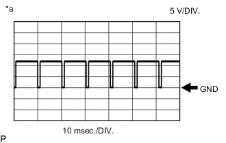
*a Reference waveform duty ratio: 88 to 92% Inspect the sub-battery module using an oscilloscope.
Tester Connection Condition Equipment Setting P6-11 (RD2) - U2-1 (-BAT) Engine switch on (IG) 5 V/DIV., 10 msec./DIV. Result Result Proceed to Duty ratio of normal waveform is 88 to 92% A No pulse waveforms or pulse output except those listed above B
A
REPLACE SUB-BATTERY MODULE ASSEMBLY Click here
B
REPLACE BACKUP RELAY Click here
-