OIL PUMP INSTALLATION
PROCEDURE
-
INSTALL TIMING CHAIN COVER SUB-ASSEMBLY
-
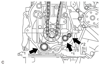
*1 Oil Pump Gasket *2 Oil Hole Cover Gasket Apply a light coat of engine oil to 2 new oil pump gaskets and a new oil hole cover gasket.
-
Install the 2 oil pump gaskets and oil hole cover gasket to the stiffening crankcase assembly.
-
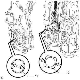
*1 Drive Rotor Spline *2 Crankshaft Timing Sprocket Align the drive rotor spline and the crankshaft timing sprocket as shown in the illustration.
-
Apply seal packing in a line to the timing chain cover sub-assembly as shown in the following illustration.
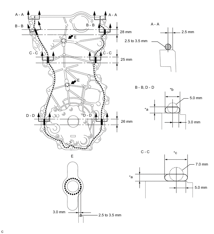
*a 3.0 mm or more *b 7.0 mm or more *c 13 mm or more - - Seal Packing Toyota Genuine Seal Packing Black, Three Bond 1207B or equivalent Seal Packing Application Chart Area Seal Packing Diameter (Round) Distance from Edge of Cover to Center of Seal Packing Seal Packing Application Length Seal Packing Dimension (Flat) Dashed Line 2.5 to 3.5 mm (0.0984 to 0.138 in.) 2.5 mm (0.0984 in.) - - (A) - (A) 2.5 to 3.5 mm (0.0984 to 0.138 in.) 2.5 mm (0.0984 in.) - - (B) - (B) 5.0 mm (0.197 in.) 3.0 mm (0.118 in.) 28 mm (1.10 in.) 7.0 mm (0.276 in.) or wider and 3.0 mm (0.118 in.) or thicker (C) - (C) 7.0 mm (0.276 in.) 5.0 mm (0.197 in.) 25 mm (0.984 in.) 13 mm (0.512 in.) or wider and 3.0 mm (0.118 in.) or thicker (D) - (D) 5.0 mm (0.197 in.) 3.0 mm (0.118 in.) 26 mm (1.02 in.) 7.0 mm (0.276 in.) or wider and 3.0 mm (0.118 in.) or thicker (E) 2.5 to 3.5 mm (0.0984 to 0.138 in.) 3.0 mm (0.118 in.) - - Note
-
Clean the surfaces with non-residue solvent before applying seal packing.
-
Install the timing chain cover sub-assembly within 3 minutes and tighten the bolts within 10 minutes of applying seal packing.
-
After applying seal packing to the timing chain cover sub-assembly, install the engine mounting bracket RH within 10 minutes.
-
Do not add oil for at least 2 hours after installation.
-
Do not start the engine for at least 2 hours after installation.
-
-
Temporarily install the timing chain cover sub-assembly with the 17 bolts and 2 nuts.
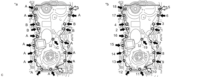
*a Torque *b Tightening Order 
Bolt 
Nut Bolt Length Item Length Thread Diameter Bolt (A) 30 mm (1.18 in.) 8.0 mm (0.315 in.) Bolt (B) 35 mm (1.38 in.) 10 mm (0.394 in.) Bolt (C) 45 mm (1.77 in.) 8.0 mm (0.315 in.) Note
Make sure there is no oil on the bolts. If oil is found on any bolt, clean it before installation.
-
Tighten the 17 bolts and 2 nuts in several steps, in the order shown in the illustration.
- Torque:
- Bolt (A), (C) and Nut
- 21 N*m { 214 kgf*cm, 15 ft.*lbf }
- Bolt (B)
- 55 N*m { 561 kgf*cm, 41 ft.*lbf }
-
-
INSTALL ENGINE MOUNTING BRACKET RH
-
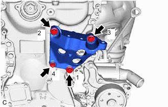
Install the engine mounting bracket RH with the 4 bolts in the order shown in the illustration.
- Torque:
- Bolt (1), (2) and (3)
- 55 N*m { 561 kgf*cm, 41 ft.*lbf }
- Bolt (4)
- 21 N*m { 214 kgf*cm, 15 ft.*lbf }
Note
After applying seal packing to the timing chain cover sub-assembly, install the engine mounting bracket RH within 10 minutes.
-
-
INSTALL TIMING CHAIN COVER OIL SEAL
-
INSTALL V-RIBBED BELT TENSIONER ASSEMBLY
-
INSTALL CAMSHAFT TIMING OIL CONTROL SOLENOID ASSEMBLY
-
INSTALL CRANKSHAFT PULLEY
-
INSTALL CRANKSHAFT POSITION SENSOR
-
INSTALL CYLINDER HEAD COVER SUB-ASSEMBLY
-
INSTALL EGR VALVE BRACKET
-
Temporarily install the 2 EGR valve brackets with the 4 bolts.
-
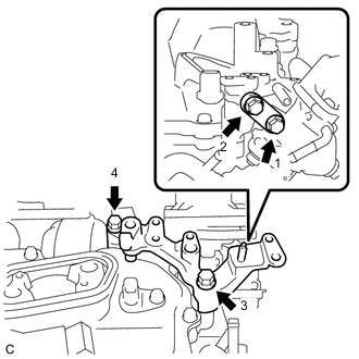
Tighten the 4 bolts in the order shown in the illustration.
- Torque:
- 21 N*m { 214 kgf*cm, 15 ft.*lbf }
-
Install the fuel hose bracket to the EGR valve bracket with the engine cover joint.
- Torque:
- 13 N*m { 133 kgf*cm, 10 ft.*lbf }
-
-
TEMPORARILY INSTALL FUEL PUMP WITH SEAL SUB-ASSEMBLY
-
TEMPORARILY INSTALL NO. 1 FUEL PIPE SUB-ASSEMBLY
-
INSTALL FUEL PUMP WITH SEAL SUB-ASSEMBLY
-
INSTALL NO. 1 FUEL PIPE SUB-ASSEMBLY
-
INSTALL NO. 1 FUEL PIPE
-
CONNECT NO. 2 FUEL TUBE SUB-ASSEMBLY
-
INSTALL FUEL PUMP PROTECTOR
-
CONNECT NO. 2 VENTILATION HOSE
-
INSTALL IGNITION COIL ASSEMBLY
-
REMOVE ENGINE ASSEMBLY FROM ENGINE STAND