ANTI-LOCK BRAKE SYSTEM(for Type B), Diagnostic DTC:C1241
| DTC Code | DTC Name |
|---|---|
| C1241 | Low Power Supply Voltage Malfunction |
DESCRIPTION
If a malfunction is detected in the power supply circuit, the skid control ECU (brake actuator assembly) stores this DTC and the fail-safe function prohibits ABS operation.
This DTC is stored when the IG1 terminal voltage deviates from the DTC detection condition due to a malfunction in the power supply or charging circuit such as the battery or alternator circuit, etc.
The DTC is cleared when the IG1 terminal voltage returns to normal.
DTC No. |
Detection Item |
DTC Detection Condition |
Trouble Area |
|---|---|---|---|
C1241 |
Low Power Supply Voltage Malfunction |
Any of the following conditions is detected:
|
|
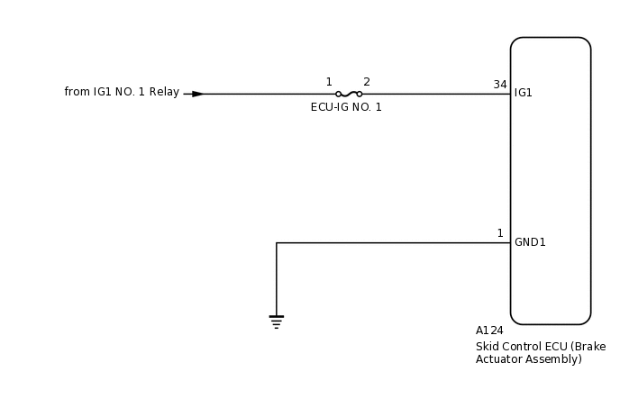
WIRING DIAGRAM
CAUTION / NOTICE / HINT
Inspect the fuses for circuits related to this system before performing the following procedure.
PROCEDURE
CHECK BATTERY
Check the battery voltage.
Standard Voltage
11 to 14 V
Result
Proceed to
OK
NG
CHECK HARNESS AND CONNECTOR (IG1 TERMINAL)
-
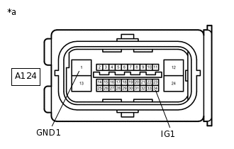
*a
Front view of wire harness connector
(to Skid Control ECU (Brake Actuator Assembly))
Make sure that there is no looseness at the locking part and the connecting part of the connector.
Disconnect the A124 skid control ECU (brake actuator assembly) connector.
Turn the ignition switch to ON.
Measure the voltage according to the value(s) in the table below.
Standard Voltage
Tester Connection
Condition
Specified Condition
A124-34 (IG1) - Body ground
Ignition switch ON
11 to 14 V
A124-34 (IG1) - A124-1 (GND1)
Ignition switch ON
11 to 14 V
Result
Proceed to
OK
NG
NG REPAIR OR REPLACE HARNESS OR CONNECTOR (IG1 CIRCUIT)
-
CHECK HARNESS AND CONNECTOR (GND1 TERMINAL)
-
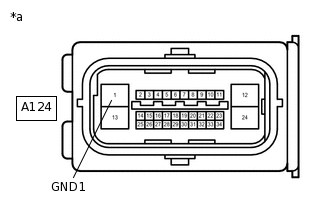
*a
Front view of wire harness connector
(to Skid Control ECU (Brake Actuator Assembly))
Turn the ignition switch off.
Measure the resistance according to the value(s) in the table below.
Standard Resistance
Tester Connection
Condition
Specified Condition
A124-1 (GND1) - Body ground
Always
Below 1 Ω
Result
Proceed to
OK
NG
NG REPAIR OR REPLACE HARNESS OR CONNECTOR (GND1 CIRCUIT)
-
RECONFIRM DTC
Reconnect the A124 skid control ECU (brake actuator assembly) connector.
Clear the DTCs.
Chassis > ABS/VSC/TRC > Clear DTCs
Turn the ignition switch off.
Start the engine.
Perform a road test.
Check if the same DTC is output.
Chassis > ABS/VSC/TRC > Trouble Codes
Result
Result
Proceed to
DTC C1241 is not output.
A
DTC C1241 is output.
B
Tip:If troubleshooting has been carried out according to Problem Symptoms Table, refer back to the table and proceed to the next step before replacing parts.