BRAKE PEDAL ADJUSTMENT
PROCEDURE
INSPECT AND ADJUST BRAKE PEDAL HEIGHT
-
Check the brake pedal height.
Pedal Height from Floor Panel
for LHD
148.5 to 158.5 mm (5.85 to 6.24 in.)
for RHD
137.9 to 147.9 mm (5.43 to 5.82 in.)
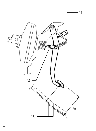
Table 1. Text in Illustration *1
Stop Light Switch
*2
Clevis Lock Nut
*3
Floor Panel
*a
Pedal Height
Adjust the brake pedal height.
Disconnect the stop light switch connector.
Remove the stop light switch assembly.
Loosen the push rod clevis lock nut.
Adjust the brake pedal height by turning the push rod.
Tighten the push rod clevis lock nut.
22 N*m
224 kgf*cm
16 ft.*lbf
Insert the stop light switch into the adjuster mounting until the switch body touches the brake pedal.
Note:Do not depress the brake pedal.
Turn the switch a quarter turn clockwise.
1.5 N*m
15 kgf*cm
13 in.*lbf
or less
Note:Do not depress the pedal.
Connect the connector to the switch.
Check the switch clearance.
Stop light switch clearance
0.5 to 2.6 mm (0.0197 to 0.102 in.)
-
INSPECT BRAKE PEDAL FREE PLAY
Stop the engine. Depress the brake pedal several times until no vacuum is left in the brake booster. Release the brake pedal.
-
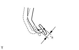
Depress the pedal until a slight resistance is felt. Measure the distance as shown in the illustration.
Pedal free play
1.0 to 6.0 mm (0.0394 to 0.236 in.)
Table 2. Text in Illustration *a
Pedal Free Play
If the pedal free play is not as specified, check the stop light switch clearance.
INSPECT BRAKE PEDAL RESERVE DISTANCE
Tip:Measure the distance from the same point used for the brake pedal height inspection.
Release the parking brake.
With the engine running, depress the brake pedal and measure the pedal reserve distance.
Pedal Reserve Distance from the Floor Panel at 294 N (30 kgf, 66 lbf)
Model
Specified Condition
for LHD
75 mm (2.95 in.)
for RHD
70 mm (2.76 in.)
If the distance is not as specified, troubleshoot the brake system (Click here).