METER / GAUGE SYSTEM Speedometer Malfunction
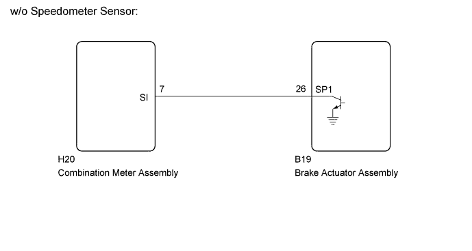
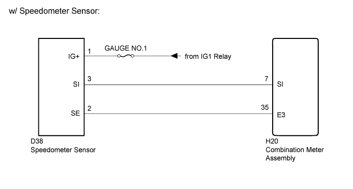
WIRING DIAGRAM
INSPECTION PROCEDURE
Note
Inspect the fuses for circuits related to this system before performing the following inspection procedure.
PROCEDURE
-
PERFORM ACTIVE TEST USING GTS (SPEED METER OPERATION)
-
Use the Active Test to check the operation of the speedometer Click here.
Combination Meter Tester Display Test Part Control Range Diagnostic Note Speed Meter Operation Speedometer OFF, 0, 40 or 80 (mph)*1
-
40 → 42.0 to 44.5
-
80 → 83.1 to 87.1
Acceptable range (mph): [Control range → Speedometer display]
OFF, 0, 40, 80, 120 or 160 (km/h)*2
-
40 → 41.7 to 46.2
-
80 → 83.4 to 88.4
-
120 → 125.1 to 130.6
-
160 → 166.2 to 173.2
Acceptable range (km/h): [Control range → Speedometer display]*3
-
40 → 41.0 to 45.5
-
80 → 82.0 to 87.0
-
120 → 122.8 to 128.3
-
160 → 163.8 to 170.3
Acceptable range (km/h): [Control range → Speedometer display]*4
-
40 → 41.3 to 45.8
-
80 → 82.6 to 87.6
-
120 → 123.9 to 128.9
-
160 → 165.2 to 170.2
Acceptable range (km/h): [Control range → Speedometer display]*5
-
40 → 40.2 to 44.5
-
80 → 80.5 to 85.5
-
120 → 120.7 to 126.2
-
160 → 160.9 to 167.4
Acceptable range (km/h): [Control range → Speedometer display]*6
-
*1: for mph
-
*2: for km/h
-
*3: except Australia
-
*4: except 1KD-FTV, Manual Transmission (for Australia)
-
*5: for 1KD-FTV, Manual Transmission (for Australia)
-
*6: for Automatic Transmission (for Australia)
OK Needle indication is normal. -
NG 
REPLACE COMBINATION METER ASSEMBLY Click here
OK 
-
-
READ VALUE USING GTS (VEHICLE SPEED METER)
-
Use the Data List to check if the speedometer is operating properly Click here.
Combination Meter Tester Display Measurement Item/Range Normal Condition Diagnostic Note Vehicle Speed Meter Vehicle speed / Min.: 0 km/h (0 mph), Max.: 255 km/h (158 mph) Almost same as actual vehicle speed - OK Vehicle speed displayed on the GTS is almost the same as the actual vehicle speed measured using a speedometer tester (calibrated chassis dynamometer). Result Result Proceed to OK A NG (w/o Speedometer Sensor) B NG (w/ Speedometer Sensor) C
B 
READ VALUE USING GTS (VEHICLE SPEED) Click here
C
CHECK COMBINATION METER ASSEMBLY Click here
A 
REPLACE COMBINATION METER ASSEMBLY Click here
-
-
READ VALUE USING GTS (VEHICLE SPEED)
-
Use the Data List to check if the speedometer is operating properly Click here.
ABS/VSC/TRC (w/ ABS) Tester Display Measurement Item/Range Normal Condition Diagnostic Note Vehicle Speed Vehicle speed / Min.: 0 km/h (0 mph), Max.: 326 km/h (202 mph) Almost same as actual vehicle speed measured using speedometer tester - OK Vehicle speed displayed on the GTS is almost the same as the actual vehicle speed measured using a speedometer tester (calibrated chassis dynamometer).
NG
GO TO ANTI-LOCK BRAKE SYSTEM Click here
OK
-
-
CHECK COMBINATION METER ASSEMBLY (OUTPUT SIGNAL)
-
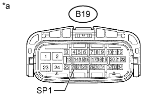
Text in Illustration *a Front view of wire harness connector
(to Brake Actuator Assembly)
Disconnect the brake actuator assembly connector.
-
Measure the voltage according to the value(s) in the table below.
Standard Voltage Tester Connection Condition Specified Condition B19-26 (SP1) - Body ground Ignition switch ON 11 to 14 V
NG
CHECK COMBINATION METER ASSEMBLY (INPUT SIGNAL) Click here
OK
-
-
CHECK COMBINATION METER ASSEMBLY (INPUT SIGNAL)
-
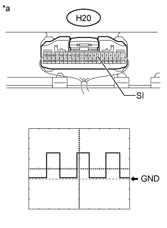
Text in Illustration *a Component with harness connected
(Combination Meter Assembly)
Check the input signal waveform using an oscilloscope.
Item Condition Tester Connection H20-7 (SI) - Body ground Tool Setting 5 V/DIV., 20 ms/DIV. Vehicle Condition Ignition switch ON, driving at approximately 20 km/h (12 mph) OK The correct waveform appears as shown in the illustration. Tech Tips
As vehicle speed increases, the cycle of the signal waveform narrows.
NG
GO TO ANTI-LOCK BRAKE SYSTEM Click here
OK
REPLACE BRAKE ACTUATOR ASSEMBLY Click here
-
-
CHECK HARNESS AND CONNECTOR (COMBINATION METER ASSEMBLY - BRAKE ACTUATOR ASSEMBLY)
-
Disconnect the H20 combination meter assembly connector.
-
Disconnect the B19 brake actuator assembly connector.
-
Measure the resistance according to the value(s) in the table below.
Standard Resistance Tester Connection Condition Specified Condition H20-7 (SI) - B19-26 (SPI) Always Below 1 Ω H20-7 (SI) or B19-26 (SPI) - Body ground Always 10 kΩ or higher
NG
REPAIR OR REPLACE HARNESS OR CONNECTOR
OK
REPLACE COMBINATION METER ASSEMBLY Click here
-
-
CHECK COMBINATION METER ASSEMBLY
-
Text in Illustration *a Component with harness connected
(Combination Meter Assembly)
Check the input signal waveform using an oscilloscope.
Item Condition Tester Connection H20-7 (SI) - Body ground Tool Setting 5 V/DIV., 20 ms/DIV. Vehicle Condition Ignition switch ON, driving at approximately 20 km/h (12 mph) OK The correct waveform appears as shown in the illustration. Tech Tips
As vehicle speed increases, the cycle of the signal waveform narrows.
NG
CHECK HARNESS AND CONNECTOR (SPEEDOMETER SENSOR - COMBINATION METER ASSEMBLY AND BATTERY) Click here
OK
REPLACE COMBINATION METER ASSEMBLY Click here
-
-
CHECK HARNESS AND CONNECTOR (SPEEDOMETER SENSOR - COMBINATION METER ASSEMBLY AND BATTERY)
-
Disconnect the D38 speedometer sensor connector.
-
Disconnect the H20 combination meter assembly connector.
-
Measure the voltage according to the value(s) in the table below.
Standard Voltage Tester Connection Switch Condition Specified Condition D38-1 (IG+) - Body ground Ignition switch ON 11 to 14 V -
Measure the resistance according to the value(s) in the table below.
Standard Resistance Tester Connection Condition Specified Condition D38-3 (SI) - H20-7 (SI) Always Below 1 Ω D38-2 (SE) - H20-35 (E3) Always Below 1 Ω D38-3 (SI) or H20-7 (SI) - Body ground Always 10 kΩ or higher D38-2 (SE) or H20-35 (E3) - Body ground Always 10 kΩ or higher Result Result Proceed to OK (for 1KD-FTV) A OK (for 2KD-FTV) B NG C
B
REPLACE SPEEDOMETER SENSOR Click here
C
REPAIR OR REPLACE HARNESS OR CONNECTOR
A
REPLACE SPEEDOMETER SENSOR Click here
-