AUTOMATIC TRANSAXLE SYSTEM
-
CONSTRUCTION
-
A 6-speed configuration has been achieved by using 2 planetary gear units, creating a 6-speed automatic transaxle.
-
A Ravigneaux type planetary gear unit is used as the rear gear unit. The gear unit consists of pairs of sun gears (front and rear) and planetary pinion gears (long and short) with different diameters within a single planetary gear.
-
A centrifugal fluid pressure canceling mechanism is used in the No. 1 clutch (C1) and No. 2 clutch (C2) that are applied when shifting between 1st to 6th gears.
-
The shapes of the grooves in the clutches and brake linings have been optimized in order to reduce drag.
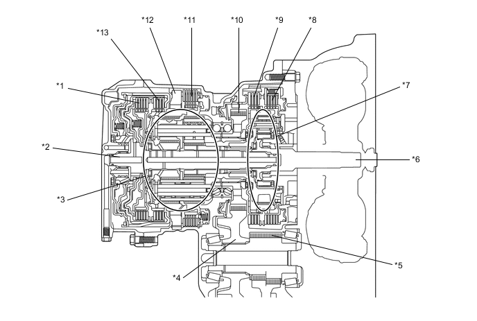
*1 No. 1 Clutch (C1) *2 Intermediate Shaft *3 Ravigneaux Planetary Gear Unit *4 Counter Driven Gear *5 Differential Drive Pinion *6 Input Shaft *7 Underdrive Planetary Gear Unit *8 No. 1 Brake (B1) *9 No. 3 Brake (B3) *10 Counter Drive Gear *11 No. 2 Brake (B2) *12 No. 1 1-way Clutch (F1) *13 No. 2 Clutch (C2) - - 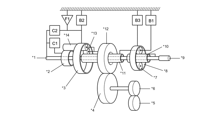
*1 Intermediate Shaft *2 Rear Sun Gear (Ravigneaux Planetary Gear Unit) *3 Ring Gear (Ravigneaux Planetary Gear Unit) *4 Counter Driven Gear *5 Ring Gear *6 Differential Drive Pinion *7 Pinion Gear (Underdrive Planetary Gear Unit) *8 Ring Gear (Underdrive Planetary Gear Unit) *9 Input Shaft *10 Sun Gear (Underdrive Planetary Gear Unit) *11 Front Sun Gear (Ravigneaux Planetary Gear Unit) *12 Counter Drive Gear *13 Short Pinion Gear (Ravigneaux Planetary Gear Unit) *14 Long Pinion Gear (Ravigneaux Planetary Gear Unit)
-
-
OPERATION
-
Transaxle Power Flow
Shift Solenoid Valves Operation Shift Lever Position and Gear Range Shift Solenoid Valve SL SL1 SL2 SL3 SL4 SLU P - ○ - - - - R ■ - - - ○ - N - ○ - - - - D 1st - ○ - - - - 2nd ○ ○ - ○ - ▲ 3rd ○ ○ - - ○ ▲ 4th ○ ○ ○ - - ▲ 5th ○ - ○ - ○ ▲ 6th ○ - ○ ○ - ▲ M6 6th ○ - ○ ○ - ▲ M5 5th ○ - ○ - ○ ▲ M4 4th ○ ○ ○ - - ▲ M3 3rd ○ ○ - - ○ ▲ M2 2nd ○ ○ - ○ - ▲ M1 1st - ○ - - - ○ Tech Tips
○: On
■: On while engaging, off after engaged
▲: In accordance with flex lock-up
-: Not operation
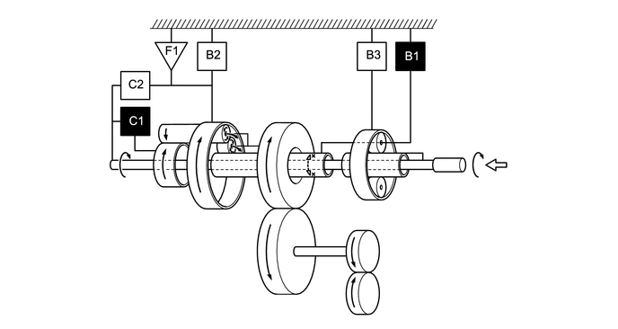
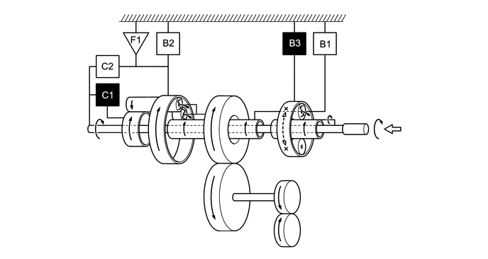
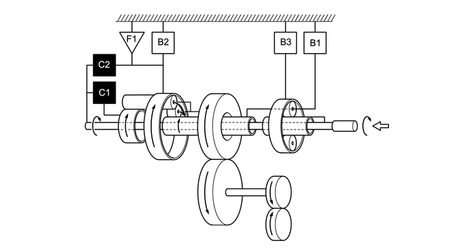
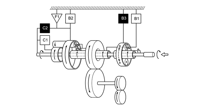
Friction Engagement Components and 1-way Clutch Operation Shift Lever Position and Gear Range Friction Engagement Component 1-way Clutch C1 C2 B1 B2 B3 F1 P - - - - - - R - - - ○ ○ - N - - - - - - D 1st ○ - - <○> - ○ 2nd ○ - ○ - - - 3rd ○ - - - ○ - 4th ○ ○ - - - - 5th - ○ - - ○ - 6th - ○ ○ - - - M6 6th - ○ ○ - - - M5 5th - ○ - - ○ - M4 4th ○ ○ - - - - M3 3rd ○ - - - ○ - M2 2nd ○ - ○ - - - M1 1st ○ - - ○ - ○ Tech Tips
○: On
<○>: During engine brake operation
-: Not operation
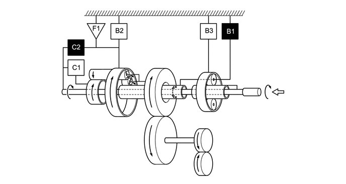
Figure 1. 1st Gear (Shift Lever in M)
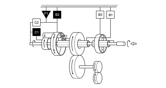

Input 
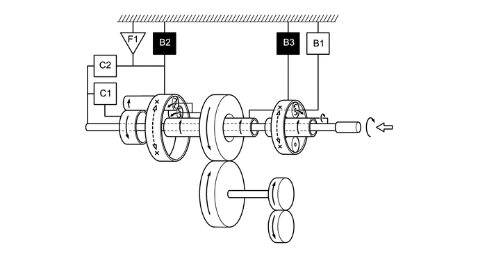
Operates Figure 2. 1st Gear (Shift Lever in D)
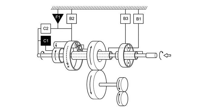
Input Operates Figure 3. 2nd Gear
Input Operates Figure 4. 3rd Gear
Input Operates Figure 5. 4th Gear
Input Operates Figure 6. 5th Gear
Input Operates Figure 7. 6th Gear
Input Operates Figure 8. Reverse Gear
Input Operates
-