UPPER INSTRUMENT PANEL INSTALLATION
CAUTION / NOTICE / HINT
Use the same procedure for RHD and LHD vehicles.
The procedure listed below is for LHD vehicles.
A bolt without a torque specification is shown in the standard bolt chart.
PROCEDURE
INSTALL UPPER INSTRUMENT PANEL
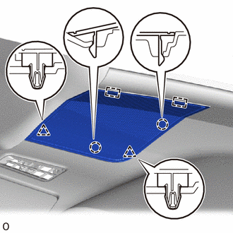
Attach the 8 clips to install the upper instrument panel.
for Single Type Airbag:
Install the 2 bolts <C> or <D>.
Install the 2 bolts <B>.
20 N*m
204 kgf*cm
15 ft.*lbf
Connect each connector.
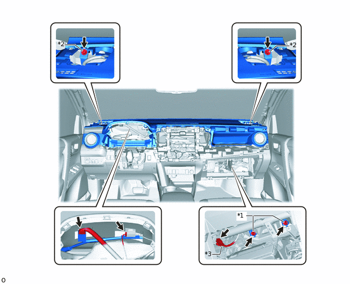
*1
Bolt <B>
*2
Bolt <C> or <D>
*3
Airbag Connector
-
-
-
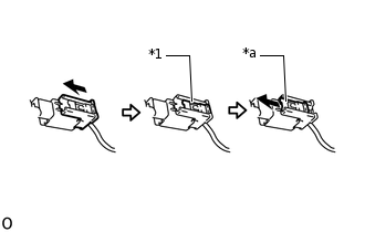
*1
Lock Slider
*a
Lock Position
Connect the airbag connector.
Note:When handling the airbag connector, take care not to damage the airbag wire harness.
Check that the lock slider is in the lock position.
for Dual Type Airbag:
Install the 2 bolts <C> or <D>.
Install the 2 bolts <B>.
20 N*m
204 kgf*cm
15 ft.*lbf
Connect each connector.
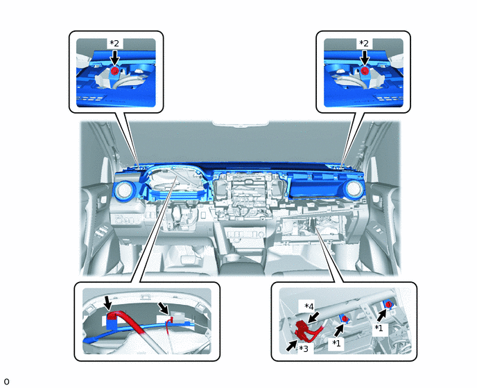
*1
Bolt <B>
*2
Bolt <C> or <D>
*3
Airbag Connector A
*4
Airbag Connector B
-
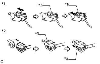
*1
Airbag Connector A
*2
Airbag Connector B
*3
Lock Slider
*a
Lock Position
Connect the 2 airbag connectors A and B.
Note:When handling the airbag connector, take care not to damage the airbag wire harness.
Check that the lock slider is in the lock position.
INSTALL FRONT PILLAR GARNISH LH (w/o Curtain Shield Airbag)
INSTALL FRONT PILLAR GARNISH RH (w/o Curtain Shield Airbag)
INSTALL FRONT PILLAR GARNISH LH (w/ Curtain Shield Airbag)
INSTALL FRONT PILLAR GARNISH RH (w/ Curtain Shield Airbag)
INSTALL FRONT NO. 2 SPEAKER ASSEMBLY
INSTALL NO. 2 SPEAKER HOLE COVER (w/o Speaker)
-
Attach the 2 guides, 2 clips and 2 claws to install the No. 2 speaker hole cover.
-
INSTALL NO. 1 SPEAKER HOLE COVER (w/o Speaker)
Tip:Use the same procedure described for the No. 2 speaker hole cover.
INSTALL NO. 2 SPEAKER HOLE COVER (w/ Speaker)
INSTALL NO. 1 SPEAKER HOLE COVER (w/ Speaker)
Tip:Use the same procedure described for the No. 2 speaker hole cover.
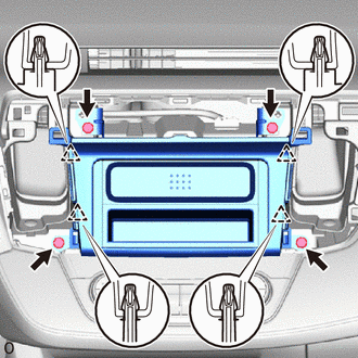
INSTALL GLOVE COMPARTMENT DOOR ASSEMBLY
-
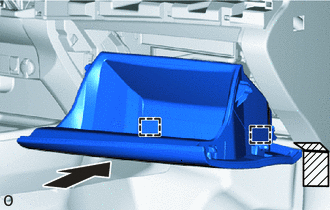

Protective Tape
Apply protective tape as shown in the illustration.
Attach the 2 hinges to install the glove compartment door assembly.
-
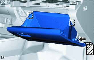
Protective Tape
While pushing in the sides of the glove compartment door assembly, attach the 2 stoppers.
Connect the glove compartment door stopper sub-assembly.
-
INSTALL UPPER INSTRUMENT CLUSTER FINISH PANEL
Attach the 4 clips to install the upper instrument cluster finish panel.
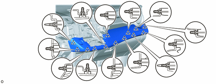
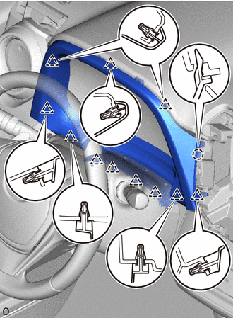
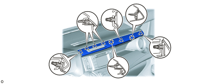
INSTALL NO. 2 INSTRUMENT PANEL GARNISH SUB-ASSEMBLY
for LHD with Entry and Start System:
Connect the connector.
Attach the 13 clips to install the No. 2 instrument panel garnish sub-assembly.
INSTALL AIR CONDITIONING CONTROL ASSEMBLY (for Automatic Air Conditioning System)
INSTALL LOWER CENTER INSTRUMENT CLUSTER FINISH PANEL SUB-ASSEMBLY (except Automatic Air Conditioning System)
Connect each connector.
-
Attach the 2 clips to install the lower center instrument cluster finish panel sub-assembly.
INSTALL HEADLIGHT DIMMER SWITCH
INSTALL COMBINATION METER ASSEMBLY
INSTALL NO. 1 INSTRUMENT CLUSTER FINISH PANEL
-
Attach the 11 clips and claw to install the No. 1 instrument cluster finish panel.
-
INSTALL STEREO OPENING COVER (w/o Audio)
-
Attach the 4 clips to install the stereo opening cover.
Install the 4 bolts.
-
INSTALL RADIO RECEIVER ASSEMBLY (w/ Radio Receiver)
INSTALL NAVIGATION RECEIVER (w/ Navigation System)
INSTALL TELLTALE LIGHT ASSEMBLY
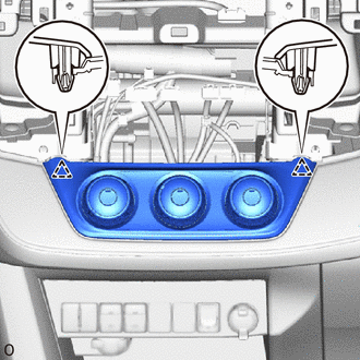
INSTALL NO. 3 INSTRUMENT PANEL REGISTER ASSEMBLY
-
Attach the 2 clips and 2 claws to install the No. 3 instrument panel register assembly.
-
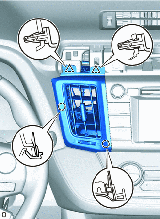
INSTALL NO. 4 INSTRUMENT PANEL REGISTER ASSEMBLY
-
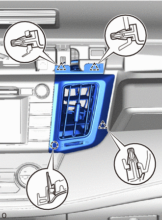
Attach the 3 clips and claw to install the No. 4 instrument panel register assembly.
-
INSTALL CENTER NO. 1 INSTRUMENT CLUSTER FINISH PANEL
Attach the 6 clips and 2 claws to install the center No. 1 instrument cluster finish panel.
CONNECT CABLE TO NEGATIVE BATTERY TERMINAL
Note:When disconnecting the cable, some systems need to be initialized after the cable is reconnected.
CHECK SRS WARNING LIGHT