WIPER AND WASHER SYSTEM TERMINALS OF ECU
-
CHECK HEADLIGHT LEVELING ECU ASSEMBLY (w/ Headlight Cleaner System)
-
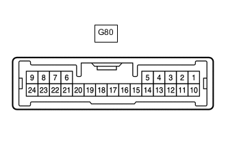
Disconnect the G80 headlight leveling ECU assembly connector.
-
Measure the resistance and voltage according to the value(s) in the table below.
Tech Tips
Measure the values on the wire harness side with the connector disconnected.
Terminal No. (Symbol) Wiring Color Terminal Description Condition Specified Condition G80-1 (IG) - Body ground G - Body ground IG power supply Ignition switch ON Below 1 V Ignition switch off 11 to 14 V G80-9 (E1) - Body ground W-B - Body ground Body ground Always Below 1 Ω -
Reconnect the G80 headlight leveling ECU assembly connector.
-
Measure the voltage according to the value(s) in the table below.
Terminal No. (Symbol) Wiring Color Terminal Description Condition Specified Condition G80-16 (HLC) - Body ground B - Body ground Headlight cleaner motor operation signal Headlight cleaner motor not operating 11 to 14 V Headlight cleaner motor operating Below 1 V G80-4 (FRWA) - Body ground LA-B - Body ground Washer switch operation signal Ignition switch ON, windshield wiper switch assembly (windshield washer switch) off 11 to 14 V Ignition switch ON, windshield wiper switch assembly (windshield washer switch) on Below 1 V
-
-
CHECK HEADLIGHT CLEANER CONTROL RELAY (w/ Headlight Cleaner System)
-
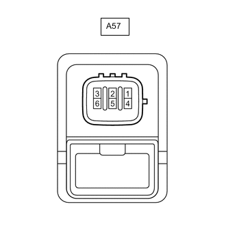
Disconnect the A57 headlight cleaner control relay connector.
-
Measure the voltage and resistance according to the value(s) in the table below.
Tech Tips
Measure the values on the wire harness side with the connector disconnected.
Terminal No. (Symbol) Wiring Color Terminal Description Condition Specified Condition A57-3 (IG) - A57-4 (E) P - W-B IG power supply Ignition switch ON 11 to 14 V Ignition switch off Below 1 V A57-4 (E) - Body ground W-B - Body ground Body ground Always Below 1 Ω -
Reconnect the A57 headlight cleaner control relay connector.
-
Measure the voltage according to the value(s) in the table below.
Terminal No. (Symbol) Wiring Color Terminal Description Condition Specified Condition A57-6 (PB) - A57-4 (E) L - W-B Headlight cleaner motor operation signal Headlight cleaner motor not operating 11 to 14 V Headlight cleaner motor operating Below 1 V
-
-
CHECK COMBINATION METER ASSEMBLY (w/ Washer Fluid Level Warning System)
-
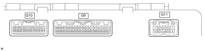
Disconnect the G9 and G10 combination meter assembly connectors.
-
Measure the resistance and voltage according to the value(s) in the table below.
Tech Tips
Measure the values on the wire harness side with the connector disconnected.
Terminal No. (Symbol) Wiring Color Terminal Description Condition Specified Condition G9-22 (IG+) - Body ground Y - Body ground IG power supply Ignition switch ON Below 1 V Ignition switch off 11 to 14 V G9-21 (B) - Body ground W - Body ground Battery Always 11 to 14 V G10-20 (GND) - Body ground W-B - Body ground Body ground Always Below 1 Ω -
Reconnect the G9 and G10 combination assembly connectors.
-
Measure the voltage according to the value(s) in the table below.
Terminal No. (Symbol) Wiring Color Terminal Description Condition Specified Condition G9-17 (WLVL) - Body ground R - Body ground Washer fluid level signal Ignition switch ON, washer fluid level not low 11 to 14 V Ignition switch ON, washer fluid level low Below 1 V
-