GENERATOR (for BOSCH Made) REASSEMBLY
-
INSTALL GENERATOR ROTOR ASSEMBLY
Note
Do not drop the generator rotor assembly.
-
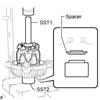
Set the spacer ring, drive end frame, generator rotor assembly and SST1 to SST2 as shown in the illustration.
- SST
- 09285-76010
- 09630-00014 ( 09631-00061 )
-
Using SST1, SST2 and a press, slowly press the generator rotor into the drive end frame and spacer ring.
-
-
INSTALL GENERATOR PULLEY
-
Fix the generator in a vise between aluminum plates.
Note
Do not damage the generator.
-
Temporarily install the washer and generator pulley with the nut.
-
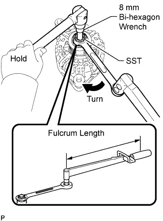
Set SST, a ball joint lock nut wrench and an 8 mm bi-hexagon wrench as shown in the illustration.
- SST
- 09820-30020
-
Hold the 8 mm bi-hexagon wrench in place and turn SST and the ball joint lock nut wrench clockwise to tighten the nut.
- Torque:
- 80 N*m { 816 kgf*cm, 59 ft.*lbf, without ball joint lock nut wrench }
- 53 N*m { 540 kgf*cm, 39 ft.*lbf, with ball joint lock nut wrench }
Note
Do not use a tool such as an impact wrench or equivalent.
Tech Tips
-
Use a torque wrench with a fulcrum length of 300 mm (11.8 in.).
-
Make sure the ball joint lock nut wrench and torque wrench are connected in a straight line.
-
Check that the generator pulley rotates smoothly.
-
-
INSTALL FITTING RING
-
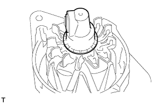
Align the 3 cutouts of the fitting ring with the stator generator with rectifier.
-
-
INSTALL GENERATOR STATOR SUB-ASSEMBLY WITH RECTIFIER
-
Align the key of the drive end frame with the keyway of the generator stator.
-

Install the stator with the 4 bolts.
- Torque:
- 4.3 N*m { 44 kgf*cm, 38 in.*lbf }
-
-
INSTALL GENERATOR REGULATOR SUB-ASSEMBLY WITH BRUSH
-
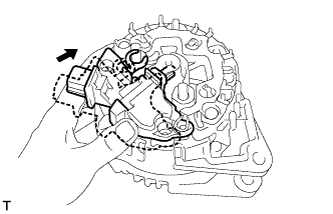
Attach the brushes and terminals to the rectifier end frame of the regulator.
-
Install the regulator with the 3 screws.
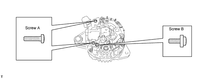
- Torque:
- 2.2 N*m { 22 kgf*cm, 19 in.*lbf, for screw A }
- 1.2 N*m { 12 kgf*cm, 11 in.*lbf, for screw B }
Tech Tips
Install screw B to the position shown in the illustration.
-
-
INSTALL GENERATOR REAR END COVER
-
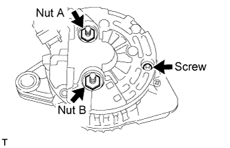
Install the rear end cover with the 2 nuts and screw.
Note
The protective tower must be attached on the end cover.
- Torque:
- 19 N*m { 194 kgf*cm, 14 ft.*lbf, for nut A }
- 12 N*m { 122 kgf*cm, 9 ft.*lbf, for nut B }
- 2.4 N*m { 24 kgf*cm, 21 in.*lbf, for screw }
-
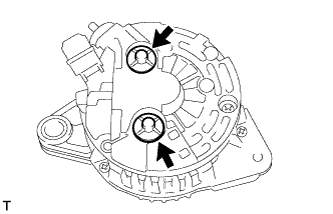
Install the 2 terminal covers by turning them clockwise.
-