INTAKE MANIFOLD INSTALLATION
PROCEDURE
INSTALL SWIRL CONTROL VALVE
Install the swirl control valve with the 3 bolts to the intake manifold.
Tip:Refer to "SPECIFICATIONS - STANDARD BOLT" for the tightening torque.
Attach the rod to the swirl control valve.
INSTALL NO. 2 EGR PIPE
Install a new O-ring to the No. 2 EGR pipe.
Install the No. 2 EGR pipe to the intake manifold.
INSTALL EGR GAS TEMPERATURE SENSOR
INSTALL GLOW PLUG CONTROLLER ASSEMBLY
INSTALL TURBO PRESSURE SENSOR
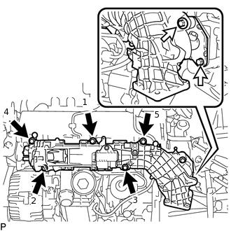
INSTALL INTAKE MANIFOLD
Install a new gasket to the No. 2 EGR pipe.
Tip:Make sure that the claw of the gasket faces the No. 2 EGR pipe.
Install 4 new gaskets to the intake manifold.
-

Bolt (A)

Bolt (B)
Temporarily install the intake manifold with the 7 bolts.
Tighten the 5 bolts (A) in the order shown in the illustration.
5.0 N*m
51 kgf*cm
44 in.*lbf
Further tighten the 5 bolts (A) in the order shown in the illustration again.
10 N*m
102 kgf*cm
7 ft.*lbf
Tighten the 2 bolts (B).
8.0 N*m
82 kgf*cm
71 in.*lbf
INSTALL NO. 1 VACUUM PIPE
Install a new O-ring to the No. 1 vacuum pipe.
Using an E7 "TORX" socket wrench, install the No. 1 vacuum pipe to the cylinder block sub-assembly with the bolt.
8.0 N*m
82 kgf*cm
71 in.*lbf
Connect the vacuum hose.
INSTALL NO. 2 VACUUM HOSE ASSEMBLY
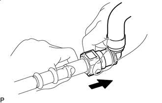
Connect the No. 2 vacuum hose assembly to the No. 1 vacuum pipe.
Check that there is no damage or contamination in the connected part of the No. 1 vacuum pipe.
Line up the No. 1 vacuum pipe and No. 2 vacuum hose assembly connector and push them together until a "click" sound is heard. If the connection is tight, apply a small amount of clean engine oil to the tip of the No. 1 vacuum pipe.
-
Pull
After connecting the No. 1 vacuum pipe and No. 2 vacuum hose assembly connector, check that the No. 1 vacuum pipe and No. 2 vacuum hose assembly connector are securely connected by pulling on them.
INSTALL ENGINE OIL LEVEL DIPSTICK GUIDE
Install a new O-ring to the engine oil level dipstick guide.
Using a T25 "TORX" socket wrench, install the engine oil level dipstick guide with the bolt.
Tip:Refer to "SPECIFICATIONS - STANDARD BOLT" for the tightening torque.
Attach the clamp and connect the fuel feed pipe sub-assembly to the engine oil level dipstick guide.
Install the engine oil level dipstick.
CONNECT ENGINE WIRE
Using a T25 "TORX" socket wrench, connect the engine wire and install the screw.
Tip:Refer to "SPECIFICATIONS - STANDARD BOLT" for the tightening torque.
Attach the 2 clamps.
Connect the 2 glow plug controller assembly connectors.
Connect the turbo pressure sensor assembly connector.
Connect the camshaft position sensor connector.
Connect the generator assembly connector.
Connect the engine coolant temperature sensor connector.
Connect the fuel pressure sensor connector.
Connect the swirl control valve connector.
Attach the 6 clamps and connect the fuel quantity control valve connector.
Connect the EGR gas temperature sensor connector.
Attach the 2 clamps and connect the glow plug controller assembly harness connector.
INSTALL ENGINE COVER
INSTALL DIESEL THROTTLE BODY ASSEMBLY
PERFORM INITIALIZATION