EXHAUST MANIFOLD W/ TURBOCHARGER INSTALLATION
PROCEDURE
INSTALL STUD BOLT
Tip:If a stud bolt is deformed or the threads are damaged, replace it.
-
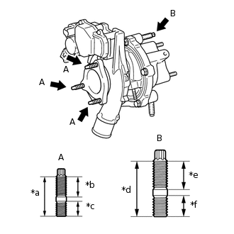
*a
27 mm (1.06 in.)
*b
16 mm (0.630 in.)
*c
9.0 mm (0.354 in.)
*d
40 mm (1.57 in.)
*e
23 mm (0.906 in.)
*f
15 mm (0.591 in.)
Using an E6 "TORX" wrench, install the 3 stud bolts (A) to the turbocharger sub-assembly.
3.0 N*m
31 kgf*cm
27 in.*lbf
Using an E10 "TORX" wrench, install the stud bolt (B) to the turbocharger sub-assembly.
22 N*m
224 kgf*cm
16 ft.*lbf
-
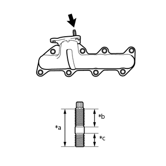
*a
41.4 mm (1.63 in.)
*b
18 mm (0.709 in.)
*c
13 mm (0.512 in.)
Using an E10 "TORX" wrench, install the stud bolt to the exhaust manifold.
22 N*m
224 kgf*cm
16 ft.*lbf
-
INSTALL EXHAUST MANIFOLD (w/o Glow Plug Controller)
Install a new exhaust manifold to head gasket to the cylinder head sub-assembly.
Install the exhaust manifold to the cylinder head sub-assembly with the 8 nuts.
43 N*m
438 kgf*cm
32 ft.*lbf
INSTALL EXHAUST MANIFOLD (w/ Glow Plug Controller)
Install a new exhaust manifold to head gasket to the cylinder head sub-assembly.
Temporarily install the No. 2 manifold support bracket to the cylinder head sub-assembly and cylinder block sub-assembly with the 2 bolts.
Temporarily install the exhaust manifold to the cylinder head sub-assembly with the 8 nuts.
-
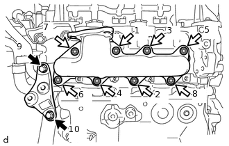

Bolt

Nut
Tighten the 2 bolts and 8 nuts in the order shown in the illustration.
Bolt
37 N*m
377 kgf*cm
27 ft.*lbf
Nut
43 N*m
438 kgf*cm
32 ft.*lbf
INSTALL INLET COMPRESSOR ELBOW SUB-ASSEMBLY
-
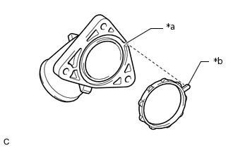
*a
Groove
*b
Protrusion
Install a new inlet compressor gasket to the inlet compressor elbow sub-assembly as shown in the illustration.
Install the inlet compressor elbow sub-assembly to the turbocharger sub-assembly with the 3 nuts.
9.0 N*m
92 kgf*cm
80 in.*lbf
-
TEMPORARILY INSTALL INLET TURBO OIL PIPE SUB-ASSEMBLY
Install a new No. 1 outlet turbo oil gasket to the cylinder block sub-assembly.
Temporarily install the inlet turbo oil pipe sub-assembly to the cylinder block sub-assembly with the 2 nuts.
INSTALL TURBOCHARGER SUB-ASSEMBLY
-
*a
Turbocharger Side
*b
Compressor Side
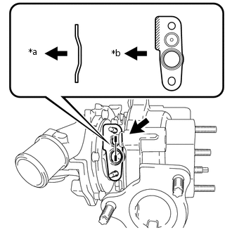
Install a new inlet turbo oil gasket to the turbocharger sub-assembly as shown in the illustration.
-
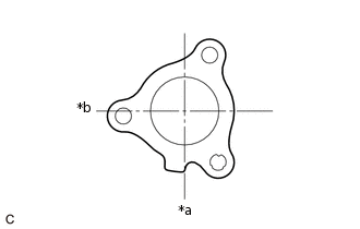
*a
RH
*b
Rear
Install a new turbo to exhaust manifold gasket to the exhaust manifold.
Install the turbocharger sub-assembly to the exhaust manifold with the 3 nuts.
53 N*m
540 kgf*cm
39 ft.*lbf
Note:When installing the turbocharger sub-assembly, do not hold it by the electric actuator rod.
Do not drop the gasket when connecting the turbo oil inlet pipe sub-assembly.
Connect the 2 turbocharger sub-assembly connectors.
-
INSTALL INLET TURBO OIL PIPE SUB-ASSEMBLY
-
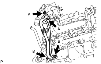
Install the inlet turbo oil pipe sub-assembly to the turbocharger sub-assembly with the 2 nuts (A).
11 N*m
112 kgf*cm
8 ft.*lbf
Tighten the 2 nuts (B).
9.0 N*m
92 kgf*cm
80 in.*lbf
-
INSTALL MANIFOLD STAY
Install the manifold stay to the turbocharger sub-assembly and cylinder block sub-assembly with the 2 bolts.
37 N*m
377 kgf*cm
27 ft.*lbf
INSTALL TURBOCHARGER STAY
Temporarily install the turbocharger stay to the turbocharger sub-assembly and cylinder head sub-assembly with the 2 bolts and nut.
-
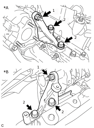
*A
w/o Glow Plug Controller
*B
w/ Glow Plug Controller
Tighten the 2 bolts and nut in the order shown in the illustration.
37 N*m
377 kgf*cm
27 ft.*lbf
INSTALL NO. 1 TURBO WATER PIPE SUB-ASSEMBLY (w/ Glow Plug Controller)
Install a new water by-pass gasket to the turbocharger sub-assembly.
Install the No. 1 turbo water pipe sub-assembly to the turbocharger sub-assembly with the 4 bolts.
11 N*m
112 kgf*cm
8 ft.*lbf
CONNECT NO. 2 TURBO WATER HOSE (w/ Glow Plug Controller)
Connect the No. 2 turbo water hose to the No. 1 turbo water pipe sub-assembly and slide the clip to secure it.
CONNECT NO. 1 TURBO WATER HOSE (w/ Glow Plug Controller)
Connect the No. 1 turbo water hose to the No. 1 turbo water pipe sub-assembly and slide the clip to secure it.
CONNECT NO. 1 AIR HOSE
-
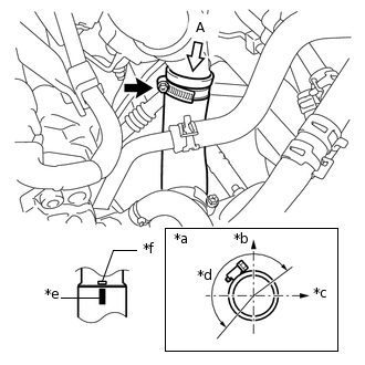
*a
View A
*b
LH
*c
Front
*d
200° (Hose Clamp Bolt Area)
*e
Paint Mark
*f
Stopper
Connect the No. 1 air hose to the turbocharger sub-assembly as shown in the illustration.
-
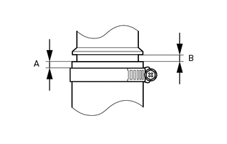
Tighten the hose clamp of the No. 1 air hose on the turbocharger sub-assembly side.
6.5 N*m
66 kgf*cm
58 in.*lbf
Note:One minute after tightening the hose clamp, check that residual torque is 3.2 N*m (33 kgf*cm, 28 in.*lbf) or more.
Tip:Push in the No. 1 air hose so that the distance (B) is 0 to 2 mm (0 to 0.0787 in.).
Position the hose clamp so that the distance (A) is 4 to 9 mm (0.157 to 0.354 in.).
-
INSTALL EXHAUST MANIFOLD CONVERTER SUB-ASSEMBLY (w/o Glow Plug Controller)
INSTALL EXHAUST MANIFOLD CONVERTER SUB-ASSEMBLY (w/ Glow Plug Controller)
CLEAR DTC (P0046)
When a new turbocharger is installed, DTC P0046 may be stored. It should be cleared by the special method.
w/o Glow Plug Controller:
w/ Glow Plug Controller:
PERFORM TURBOCHARGER INITIALIZATION
w/o Glow Plug Controller:
w/ Glow Plug Controller: