STOP AND START SYSTEM Air Conditioning Control Panel Circuit
| DTC Code | DTC Name |
|---|---|
| Air Conditioning Control Panel Circuit |
DESCRIPTION
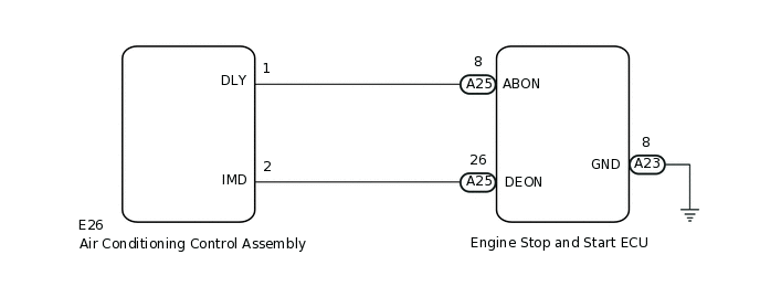
The air conditioning control assembly transmits the operation signal of each switch to the engine stop and start ECU.
WIRING DIAGRAM
PROCEDURE
READ VALUE USING GTS
Connect the GTS to the DLC3.
Turn the ignition switch to ON.
Turn the GTS on.
Enter the following menus: Powertrain / Stop and Start / Data List / A/C & Blower & Defroster SW and A/C & Blower SW.
According to the display on the GTS, read the Data List.
OK
Tester Display
Condition
Normal Condition
A/C & Blower & Defroster SW
A/C, blower (bower level 2 or more) and defroster switches on
ON
A/C, blower or defroster switch off
OFF
A/C & Blower SW
A/C and blower (bower level 2 or more) switches on
ON
A/C or blower switch off
OFF
Powertrain > Stop and Start > Data List
Tester Display
A/C & Blower & Defroster SW
A/C & Blower SW
Result
Result
Proceed to
NG (A/C & Blower & Defroster SW)
A
NG (A/C & Blower SW)
B
OK
C
B CHECK HARNESS AND CONNECTOR (ENGINE STOP AND START ECU - AIR CONDITIONING CONTROL ASSEMBLY)Click here
CHECK HARNESS AND CONNECTOR (ENGINE STOP AND START ECU - AIR CONDITIONING CONTROL ASSEMBLY)
Disconnect the A25 engine stop and start ECU connector.
Disconnect the E26 air conditioning control assembly connector.
Measure the resistance according to the value(s) in the table below.
Standard Resistance
Tester Connection
Condition
Specified Condition
A25-26 (DEON) - E26-2 (IMD)
Always
Below 1 Ω
A25-26 (DEON) - Body ground
Always
10 kΩ or higher
E26-2 (IMD) - Body ground
Always
10 kΩ or higher
Result
Proceed to
OK
NG
NG REPAIR OR REPLACE HARNESS OR CONNECTOR
CHECK ENGINE STOP AND START ECU (DEON TERMINAL VOLTAGE)
Disconnect the E26 air conditioning control assembly connector.
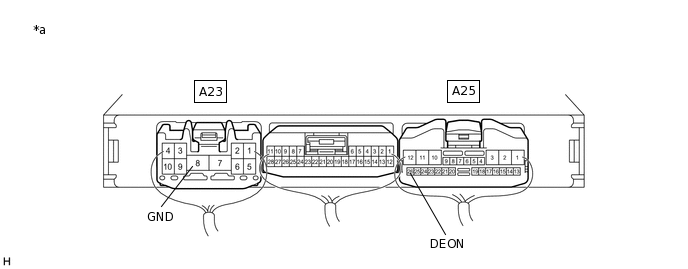
*a
Component with harness connected
(Engine Stop and Start ECU)
-
-
Turn the ignition switch to ON.
Measure the voltage according to the value(s) in the table below.
Standard Voltage
Tester Connection
Condition
Specified Condition
A25-26 (DEON) - A23-8 (GND)
Ignition switch ON
11 to 14 V
Result
Proceed to
OK
NG
CHECK HARNESS AND CONNECTOR (ENGINE STOP AND START ECU - AIR CONDITIONING CONTROL ASSEMBLY)
Disconnect the A25 engine stop and start ECU connector.
Disconnect the E26 air conditioning control assembly connector.
Measure the resistance according to the value(s) in the table below.
Standard Resistance
Tester Connection
Condition
Specified Condition
A25-8 (ABON) - E26-1 (DLY)
Always
Below 1 Ω
A25-8 (ABON) - Body ground
Always
10 kΩ or higher
E26-1 (DLY) - Body ground
Always
10 kΩ or higher
Result
Proceed to
OK
NG
NG REPAIR OR REPLACE HARNESS OR CONNECTOR
CHECK ENGINE STOP AND START ECU (ABON TERMINAL VOLTAGE)
Disconnect the E26 air conditioning control assembly connector.
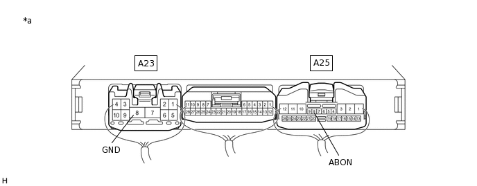
*a
Component with harness connected
(Engine Stop and Start ECU)
-
-
Turn the ignition switch to ON.
Measure the voltage according to the value(s) in the table below.
Standard Voltage
Tester Connection
Condition
Specified Condition
A25-8 (ABON) - A23-8 (GND)
Ignition switch ON
11 to 14 V
Result
Proceed to
OK
NG