BACK DOOR CLOSER SYSTEM TERMINALS OF ECU
CHECK MULTIPLEX NETWORK DOOR ECU
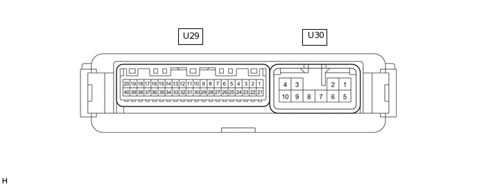
Disconnect the U29 and U30 multiplex network door ECU connectors.
Measure the voltage and resistance according to the value(s) in the table below.
Terminal No. (Symbol)
Wiring Color
Terminal Description
Condition
Specified Condition
U29-20 (ECUB) - Body ground
W - Body ground
Auxiliary battery power supply
Power switch off
11 to 14 V
U29-18 (IG) - Body ground
W - Body ground
IG power supply
Power switch on (IG)
11 to 14 V
U29-18 (IG) - Body ground
W - Body ground
IG power supply
Power switch off
Below 1 V
U30-1 (B) - Body ground
W - Body ground
Auxiliary battery power supply
Power switch off
11 to 14 V
U30-10 (GND) - Body ground
W-B - Body ground
Body ground
Always
Below 1 Ω
Reconnect the U29 and U30 multiplex network door ECU connectors.
Measure the voltage according to the value(s) in the table below.
Terminal No. (Symbol)
Wiring Color
Terminal Description
Condition
Specified Condition
U30-4 (DC+) - U30-3 (DC-)
B - R
Back door lock assembly (back door lock motor) circuit
Back door lock motor operating
11 to 14 V
U30-4 (DC+) - U30-3 (DC-)
B - R
Back door lock assembly (back door lock motor) circuit
Back door lock motor not operating
Below 1 V
U29-11 (FUL) - Body ground
W - Body ground
Back door lock assembly (back door courtesy switch) signal circuit
Back door closed → open
11 to 14 V → Below 1 V
U29-9 (HAF) - Body ground
G - Body ground
Back door lock assembly (latch switch) signal circuit
Back door closed → fully open
11 to 14 V → Below 1 V
U29-13 (PAWL) - Body ground
W - Body ground
Back door lock assembly (pawl switch) signal circuit
Back door fully open → Partially close → back door fully close → power back door operate stop
Below 1 V → 11 to 14 V → 11 to 14 V → Below 1 V
U29-7 (POS) - Body ground
GR - Body ground
Back door lock assembly (sector switch) signal circuit
Back door open → Back door closer operates → Back door closed
Below 1 V → 11 to 14 V → Below 1 V
CHECK CERTIFICATION ECU (SMART KEY ECU ASSEMBLY)
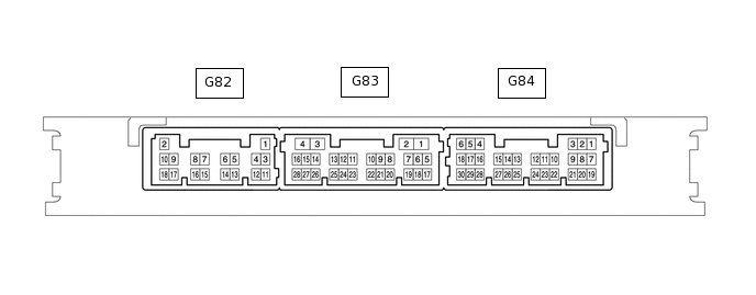
Disconnect the G82 and G84 certification ECU (smart key ECU assembly) connectors.
Measure the voltage and resistance according to the value(s) in the table below.
Terminal No. (Symbol)
Wiring Color
Terminal Description
Condition
Specified Condition
G82-2 (+B) - Body ground
W - Body ground
Auxiliary battery power supply
Power switch off
11 to 14 V
G82-10 (CUTB) - Body ground
P - Body ground
Auxiliary battery power supply
Power switch off
11 to 14 V
G84-5 (IG) - Body ground
LG - Body ground
IG power supply
Power switch on (IG)
11 to 14 V
G84-5 (IG) - Body ground
LG - Body ground
IG power supply
Power switch off
Below 1 V
G82-11 (E) - Body ground
BR - Body ground
Body ground
Always
Below 1 Ω
Reconnect the G82 and G84 certification ECU (smart key ECU assembly) connectors.
Measure the voltage according to the value(s) in the table below.
Terminal No. (Symbol)
Wiring Color
Terminal Description
Condition
Specified Condition
G83-27 (TSW5) - Body ground
Y - Body ground
Back door opener switch assembly signal
Back door opener switch assembly off
Pulse generation
G83-27 (TSW5) - Body ground
Y - Body ground
Back door opener switch assembly signal
Back door opener switch assembly on
Below 1 V
-
*1
Main Body ECU (Multiplex Network Body ECU)
-
-
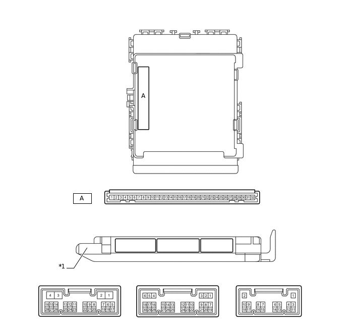
CHECK MAIN BODY ECU (MULTIPLEX NETWORK BODY ECU) AND INSTRUMENT PANEL JUNCTION BLOCK ASSEMBLY
Remove the main body ECU (multiplex network body ECU).
for RHD:Click here
for LHD:Click here
Connect the instrument panel junction block assembly connectors.
Measure the voltage and resistance according to the value(s) in the table below.
Terminal No. (Symbol)
Wiring Color
Terminal Description
Condition
Specified Condition
A-30 (BECU) -Body ground
None - Body ground
Auxiliary battery power supply
Power switch off
11 to 14 V
A-29 (ACC) -Body ground
None - Body ground
ACC power supply
Power switch on (ACC)
11 to 14 V
A-29 (ACC) -Body ground
None - Body ground
ACC power supply
Power switch off
Below 1 V
A-32 (IG) - Body ground
None - Body ground
IG power supply
Power switch on (IG)
11 to 14 V
A-32 (IG) - Body ground
None - Body ground
IG power supply
Power switch off
Below 1 V
A-11 (GND1) - Body ground
None - Body ground
Body ground
Always
Below 1 Ω