MONOLITHIC CONVERTER(w/o Glow Plug Controller) REMOVAL
PROCEDURE
PRECAUTION
Note:After turning the ignition switch off, waiting time may be required before disconnecting the cable from the negative (-) battery terminal. Therefore, make sure to read the disconnecting the cable from the negative (-) battery terminal notice before proceeding with work.
DISCONNECT CABLE FROM NEGATIVE BATTERY TERMINAL
Note:When disconnecting the cable, some systems need to be initialized after the cable is reconnected.
REMOVE NO. 1 ENGINE COVER (w/ No. 1 Engine Cover)
REMOVE WINDSHIELD WIPER MOTOR AND LINK ASSEMBLY
REMOVE WATER GUARD PLATE LH (for LHD)
for Sedan:
for Hatchback, Wagon:
REMOVE WATER GUARD PLATE LH (for RHD)
for Sedan:
for Hatchback, Wagon:
REMOVE NO. 2 HEATER AIR DUCT SPLASH SHIELD SEAL (for LHD)
for Sedan:
for Hatchback, Wagon:
REMOVE NO. 2 HEATER AIR DUCT SPLASH SHIELD SEAL (for RHD)
for Sedan:
for Hatchback, Wagon:
REMOVE OUTER COWL TOP PANEL (for LHD)
for Sedan:
for Hatchback, Wagon:
REMOVE OUTER COWL TOP PANEL (for RHD)
for Sedan:
for Hatchback, Wagon:
REMOVE BATTERY
REMOVE AIR CLEANER CAP SUB-ASSEMBLY
REMOVE AIR CLEANER CASE SUB-ASSEMBLY
REMOVE NO. 1 AIR TUBE
REMOVE FRONT CENTER FLOOR BRACE SUB-ASSEMBLY
REMOVE FRONT EXHAUST PIPE ASSEMBLY
-
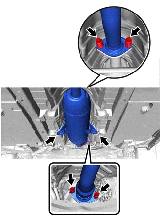
Remove the 4 bolts and 4 compression springs.
Remove the front exhaust pipe assembly from the 2 exhaust pipe supports.
Remove the 2 gaskets from the front exhaust pipe assembly and No. 2 exhaust manifold converter sub-assembly.
-
REMOVE FRONT NO. 1 FLOOR HEAT INSULATOR
REMOVE HARNESS BRACKET
REMOVE NO. 1 TURBO INSULATOR
-
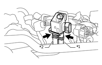
*1
Vacuum Transmitting Hose Assembly
*2
No. 2 Vacuum Transmitting Hose Assembly
Slide the 2 clips and disconnect the vacuum transmitting hose assembly and No. 2 vacuum transmitting hose assembly remove the differential pressure sensor assembly.
-
Remove the 3 bolts and No. 1 turbo insulator.
-
REMOVE AIR FUEL RATIO SENSOR
REMOVE NO. 2 VACUUM TRANSMITTING HOSE ASSEMBLY
-
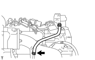
Slide the clip and remove the No. 2 vacuum transmitting hose assembly from the No. 2 vacuum pipe.
-
REMOVE VACUUM TRANSMITTING HOSE ASSEMBLY
-
Slide the clip and remove the vacuum transmitting hose assembly from the No. 1 vacuum pipe.
-
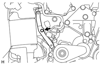
REMOVE NO. 2 VACUUM PIPE
-
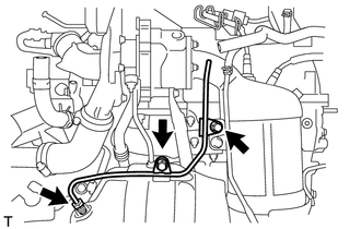
Remove the 2 bolts.
Using a 14 mm union nut wrench, remove the No. 2 vacuum pipe.
-
REMOVE DRIVE SHAFT HEAT INSULATOR SUB-ASSEMBLY
-
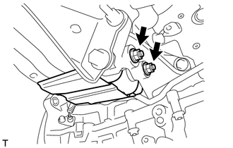
Remove the 2 nuts and drive shaft heat insulator sub-assembly from the manifold support bracket.
-
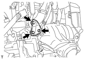
REMOVE NO. 4 MANIFOLD SUPPORT BRACKET
-
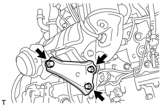
Remove the 3 bolts and No. 4 manifold support bracket from the No. 1 converter support bracket and No. 2 exhaust manifold converter sub-assembly.
-
REMOVE NO. 3 MANIFOLD SUPPORT BRACKET
-
Remove the 3 bolts and No. 3 manifold support bracket from the No. 2 manifold support bracket and No. 2 exhaust manifold converter sub-assembly.
-
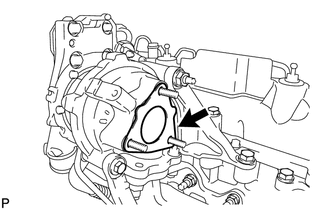
REMOVE NO. 2 EXHAUST MANIFOLD CONVERTER SUB-ASSEMBLY
-
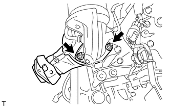
Remove the 2 nuts and No. 2 exhaust manifold converter sub-assembly from the exhaust manifold converter sub-assembly.
Remove the gasket from the exhaust manifold converter sub-assembly.
-
REMOVE NO. 1 VACUUM PIPE
Remove the bolt.
-
Using a 14 mm union nut wrench, remove the No. 1 vacuum pipe from the exhaust manifold converter sub-assembly.
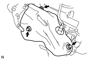
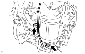
REMOVE EXHAUST MANIFOLD CONVERTER SUB-ASSEMBLY
-
Disengage the 2 wire harness clamps from the wire harness bracket.
-
Remove the bolt and harness bracket.
-
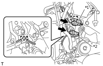
*1
Exhaust Gas Temperature Sensor Connector
*2
No. 2 Exhaust Gas Temperature Sensor Connector
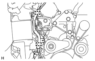
Disconnect the exhaust gas temperature sensor connector and No. 2 exhaust gas temperature sensor connector.
Disengage the 2 wire harness clamps from the wire harness bracket and cylinder block side cover.
-
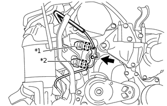
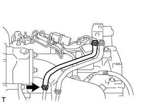
*1
Exhaust Gas Temperature Sensor Connector
*2
No. 2 Exhaust Gas Temperature Sensor Connector
Separate the exhaust gas temperature sensor connector and No. 2 exhaust gas temperature sensor connector from the wire harness bracket.
Remove the bolt and wire harness bracket.
-
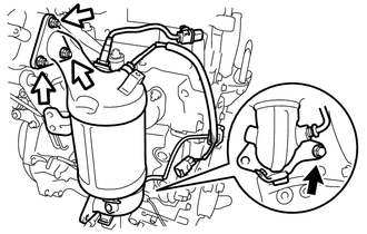

Bolt

Nut
Remove the bolt, 3 nuts and exhaust manifold converter sub-assembly.
-
Remove the gasket from the turbocharger sub-assembly.
-
REMOVE EXHAUST GAS TEMPERATURE SENSOR
REMOVE NO. 2 EXHAUST GAS TEMPERATURE SENSOR