INPUT SHAFT REASSEMBLY
PROCEDURE
INSTALL FRONT INPUT SHAFT BEARING
-
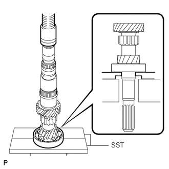
Using SST and a press, install the front input shaft bearing to the input shaft.
09527-21011
-
INSTALL 3RD GEAR NEEDLE ROLLER BEARING
-
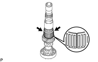
Coat the 2 pieces of the 3rd gear needle roller bearing with gear oil and install them to the input shaft.
-
INSTALL 3RD GEAR
-
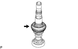
Coat the 3rd gear with gear oil and install it to the input shaft.
-
INSTALL NO. 3 SYNCHRONIZER RING
-
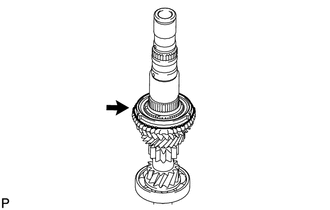
Coat the No. 3 synchronizer ring with gear oil and install it to the 3rd gear.
-
INSTALL NO. 2 TRANSMISSION CLUTCH HUB
Coat the No. 2 transmission clutch hub with gear oil.
-
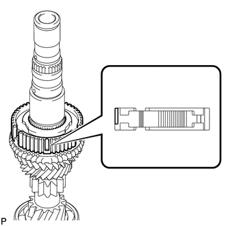
Temporarily install the No. 2 transmission clutch hub to the input shaft.
Note:Position the No. 2 transmission clutch hub correctly as shown in the illustration.
-
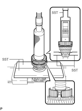
Using SST and a press, install the No. 2 transmission clutch hub to the input shaft.
09527-21011
09316-60011
09316-00011
Note:When installing the No. 2 transmission clutch hub, align the protrusion of the No. 3 synchronizer ring with the cutout of the No. 2 transmission clutch hub.
INSTALL NO. 2 CLUTCH HUB SETTING SHAFT SNAP RING
Select a new snap ring that will allow minimal axial play.
Standard clearance
0.1 mm (0.00394 in.) or less
Standard Snap Ring Thickness
Mark
Specified Condition
Mark
Specified Condition
0
2.27 mm (0.0894 in.)
4
2.47 mm (0.0972 in.)
1
2.32 mm (0.0913 in.)
5
2.52 mm (0.0992 in.)
2
2.37 mm (0.0933 in.)
6
2.57 mm (0.101 in.)
3
2.42 mm (0.0953 in.)
7
2.62 mm (0.103 in.)
-
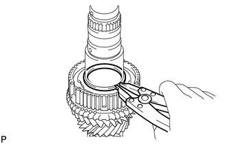
Using a snap ring expander, install the No. 2 clutch hub setting shaft snap ring.
Note:Be sure to properly install the snap ring as it easily expands.
Do not damage the journal surface of the snap ring.
INSTALL NO. 2 SYNCHROMESH SHIFTING KEY
-
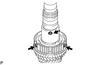
Install the 3 No. 2 synchromesh shifting keys to the No. 2 transmission clutch hub.
-
INSTALL NO. 2 TRANSMISSION HUB SLEEVE
Coat the No. 2 transmission hub sleeve with gear oil.
-
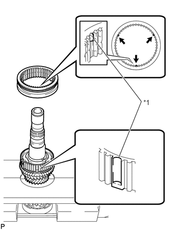
Install the No. 2 transmission hub sleeve to the No. 2 transmission clutch hub.
Table 1. Text in Illustration *1
Align
Note:When installing the No. 2 transmission hub sleeve, align the protrusions of the No. 2 transmission hub sleeve with the cutouts of the No. 2 transmission clutch hub.
INSTALL 4TH GEAR BEARING SPACER
-
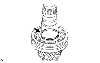
Install the 4th gear bearing spacer to the input shaft.
-
INSTALL 4TH GEAR NEEDLE ROLLER BEARING
-
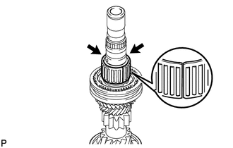
Coat the 2 pieces of the 4th gear needle roller bearing and 4th gear bearing spacer with gear oil and install the 4th gear needle roller bearing to the input shaft.
-
INSTALL OUTER 2ND SYNCHRONIZER RING
-
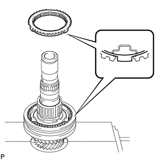
Coat the outer 2nd synchronizer ring with gear oil and install it to the No. 2 transmission clutch hub.
Note:When installing the outer 2nd synchronizer ring, align the protrusion of the outer 2nd synchronizer ring with the cutout of the No. 2 transmission clutch hub.
-
INSTALL 4TH GEAR
-
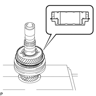
Coat the 4th gear with gear oil and install it to the input shaft.
Note:Install the 4th gear as shown in the illustration.
-
INSTALL INNER 5TH GEAR BEARING RACE LOCK BALL
-
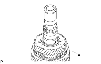
Coat the inner 5th gear bearing race lock ball with gear oil and install it to the input shaft.
-
INSTALL INNER 5TH GEAR BEARING RACE
-
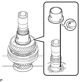
Coat the inner 5th gear bearing race with gear oil and install it to the input shaft.
Note:Align the groove of the inner 5th gear bearing race with the ball.
-
INSTALL 5TH GEAR NEEDLE ROLLER BEARING
-
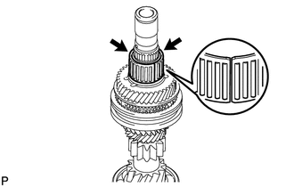
Coat the 2 pieces of the 5th gear needle roller bearing and inner 5th gear bearing race with gear oil and install the 5th gear needle roller bearing to the input shaft.
-
INSTALL 5TH GEAR
-
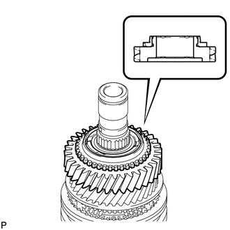
Coat the 5th gear with gear oil and install it to the input shaft.
Note:Install the 5th gear as shown in the illustration.
-
INSTALL NO. 5 SYNCHRONIZER RING
-
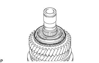
Coat the No. 5 synchronizer ring with gear oil and install it to the 5th gear.
-
INSTALL NO. 3 TRANSMISSION CLUTCH HUB
Coat the No. 3 transmission clutch hub with gear oil.
-
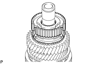
Temporarily install the No. 3 transmission clutch hub to the input shaft.
Note:Position the No. 3 transmission clutch hub correctly as shown in the illustration.
-
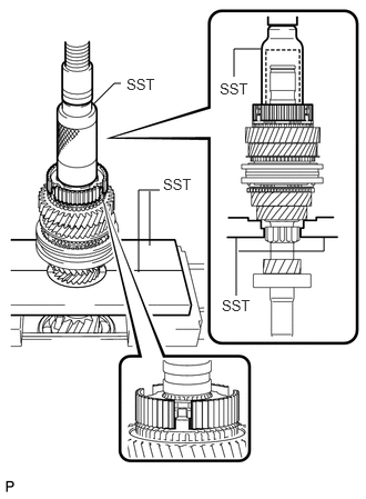
Using SST and a press, install the No. 3 transmission clutch hub to the input shaft.
09309-37010
09527-21011
Note:When installing the No. 3 transmission clutch hub, align the protrusion of the No. 5 synchronizer ring with the cutout of the No. 3 transmission clutch hub.
INSTALL NO. 3 SYNCHROMESH SHIFTING KEY
-
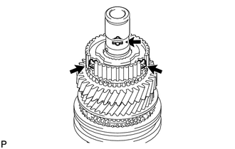
Install the 3 No. 3 synchromesh shifting keys to the No. 3 transmission clutch hub.
-
INSTALL NO. 3 TRANSMISSION HUB SLEEVE
-
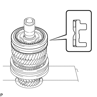
Coat the No. 3 transmission hub sleeve with gear oil.
Install the No. 3 transmission hub sleeve to the No. 3 transmission clutch hub.
Note:Install the No. 3 transmission hub sleeve as shown in the illustration.
-
INSTALL INNER 6TH GEAR BEARING RACE LOCK BALL
-
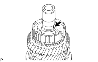
Coat the inner 6th gear bearing race lock ball with gear oil and install it to the input shaft.
-
INSTALL INNER 6TH GEAR BEARING RACE
-
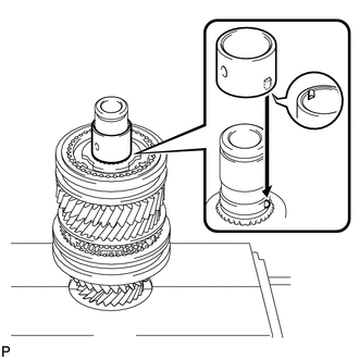
Coat the inner 6th gear bearing race with gear oil and install it to the input shaft.
Note:Align the groove of the inner 6th gear bearing race with the ball.
-
INSTALL 6TH GEAR NEEDLE ROLLER BEARING
-
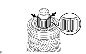
Coat the 2 pieces of the 6th gear needle roller bearing and inner 6th gear bearing race with gear oil and install the 6th gear needle roller bearing to the input shaft.
-
INSTALL NO. 5 SYNCHRONIZER RING
-
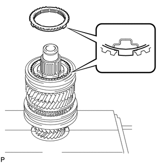
Coat the No. 5 synchronizer ring with gear oil and install it to the No. 3 transmission clutch hub.
Note:When installing the No. 5 synchronizer ring, align the protrusion of the No. 5 synchronizer ring with the cutout of the No. 3 transmission clutch hub.
-
INSTALL 6TH GEAR SUB-ASSEMBLY
-
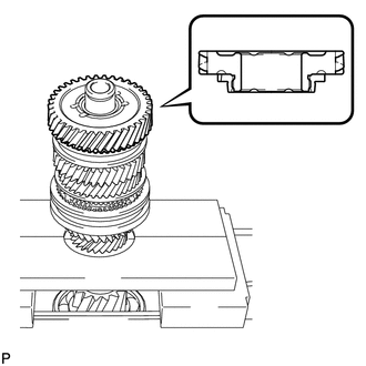
Coat the 6th gear sub-assembly with gear oil and install it to the input shaft.
Note:Install the 6th gear sub-assembly as shown in the illustration.
-
INSTALL REAR INPUT SHAFT RADIAL BALL BEARING
-
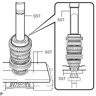
Using SST and a press, install the rear input shaft radial ball bearing to the input shaft.
09527-21011
09608-04031
-
INSTALL REAR INPUT SHAFT BEARING SHAFT SNAP RING
Select a new snap ring that will allow minimal axial play.
Standard clearance
0.1 mm (0.00394 in.) or less
Standard Snap Ring Thickness
Mark
Specified Condition
Mark
Specified Condition
A
1.65 mm (0.0649 in.)
H
2.00 mm (0.0787 in.)
B
1.70 mm (0.0669 in.)
J
2.05 mm (0.0807 in.)
C
1.75 mm (0.0689 in.)
K
2.10 mm (0.0827 in.)
D
1.80 mm (0.0709 in.)
L
2.15 mm (0.0846 in.)
E
1.85 mm (0.0728 in.)
M
2.20 mm (0.0866 in.)
F
1.90 mm (0.0748 in.)
N
2.25 mm (0.0886 in.)
G
1.95 mm (0.0768 in.)
P
2.30 mm (0.0906 in.)
-
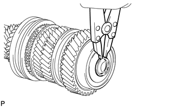
Using a snap ring expander, install the rear input shaft bearing shaft snap ring.
Note:Be sure to properly install the snap ring as it easily expands.
Do not damage the journal surface of the snap ring.
INSPECT 3RD GEAR RADIAL CLEARANCE
INSPECT 4TH GEAR RADIAL CLEARANCE
INSPECT 5TH GEAR RADIAL CLEARANCE
INSPECT 6TH GEAR RADIAL CLEARANCE
INSPECT 3RD GEAR THRUST CLEARANCE
INSPECT 4TH GEAR THRUST CLEARANCE
INSPECT 5TH GEAR THRUST CLEARANCE
INSPECT 6TH GEAR THRUST CLEARANCE