NAVIGATION SYSTEM(for Radio and Display Type) Parking Brake Switch Circuit
| DTC Code | DTC Name |
|---|---|
| Parking Brake Switch Circuit |
DESCRIPTION
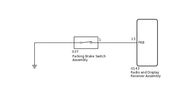
This circuit includes the parking brake switch assembly and radio and display receiver assembly.
WIRING DIAGRAM
CAUTION / NOTICE / HINT
Check that the wire harness is properly installed and does not have any sharp bends, pinching or loose connections.
PROCEDURE
CHECK VEHICLE SIGNAL (OPERATION CHECK)
-
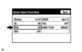
Display the "Vehicle Signal Check Mode" screen.
Check that the display changes between ON and OFF according to the parking brake operation.
OK
Parking Brake Condition
Display
Applied
ON
Released
OFF
Tip:This display is updated once per second. As a result, it is normal for the display to lag behind the actual parking brake operation.
Result
Proceed to
OK
NG
-
CHECK HARNESS AND CONNECTOR (RADIO AND DISPLAY RECEIVER ASSEMBLY - PARKING BRAKE SWITCH ASSEMBLY)
Disconnect the G143 radio and display receiver assembly connector.
Disconnect the G37 parking brake switch assembly connector.
Measure the resistance according to the value(s) in the table below.
Standard Resistance
Tester Connection
Condition
Specified Condition
G143-15 (PKB) - G37-1
Always
Below 1 Ω
G143-15 (PKB) - Body ground
Always
10 kΩ or higher
Result
Proceed to
OK
NG
NG REPAIR OR REPLACE HARNESS OR CONNECTOR
INSPECT PARKING BRAKE SWITCH ASSEMBLY
Remove the parking brake switch assembly.
Inspect the parking brake switch assembly.
Result
Proceed to
OK
NG