FUEL INJECTOR INSPECTION
PROCEDURE
INSPECT FUEL INJECTOR ASSEMBLY
-

*a
Component without harness connected
(Fuel Injector Assembly)
Measure the resistance according to the value(s) in the table below.
Standard Resistance
Tester Connection
Condition
Specified Condition
1 - 2
20°C (68°F)
11.6 to 12.4 Ω
If the result is not as specified, replace the fuel injector assembly.
Inspect the fuel injector assembly injection.
CAUTION:Keep the fuel injector assembly away from sparks during the test.
Disconnect the fuel tube sub-assembly.
-
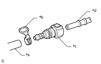
*a
SST (Hose)
*b
SST (Hose Band)
*c
SST (Fuel Tube Connector)
*d
Fuel Pipe (Vehicle Side)
Connect SST (fuel tube connector) to SST (hose) with SST (hose band), and then connect them to the fuel pipe (vehicle side).
09268-31015
09268-41500
09268-41700
95336-08070
Apply a light coat of gasoline to a new O-ring. Then install the O-ring onto the fuel injector assembly.
-
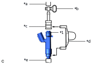
*1
O-ring
*a
SST (Hose)
*b
SST (Hose Band)
*c
SST (Adapter)
*d
SST (Clamp)
*e
Vinyl Tube
Connect SST (adapter) and SST (hose) to the fuel injector assembly, and hold them with SST (clamp).
09268-31015
09268-41141
09268-41410
09268-41700
95336-08070
-
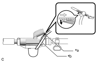
*a
Lock
*b
SST (Tie Band)
Tie SST (clamp) and SST (adapter) together with SST (tie band) as shown in the illustration.
09268-31015
09268-41800
Note:As SST (tie band) does not completely prevent SST (clamp) from becoming loose, do not subject the parts to any impacts while using them.
Before using SST (tie band), make sure that there is no wear, damage or cracks. If there are any abnormalities, replace SST.
Tip:When removing SST (tie band), disengage the lock.
Check that SST (clamp) and SST (adapter) cannot be easily separated.
Install a vinyl tube onto the fuel injector assembly.
CAUTION:Install a suitable vinyl tube onto the fuel injector assembly to prevent fuel from spraying.
Set the fuel injector assembly in a graduated cylinder.
Connect the cable to the negative (-) battery terminal.
Connect the GTS to the DLC3.
Turn the ignition switch on (IG).
Note:Do not start the engine.
Turn the GTS on.
Enter the following menus: Powertrain / Engine and ECT / Active Test / Control the Fuel Pump / Speed.
Powertrain > Engine and ECT > Active Test
Tester Display
Control the Fuel Pump / Speed
-
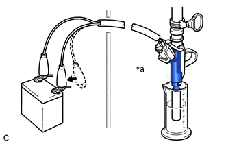
*a
SST (EFI Inspection Wire I)
Connect SST (EFI inspection wire I) to the fuel injector assembly and battery for 15 seconds, and measure the injection volume with the graduated cylinder. Test each fuel injector assembly 2 or 3 times.
09842-30090
Standard Injection Volume
Battery Connection
Condition
Specified Condition
Positive (+) battery terminal - Negative (-) battery terminal
Per 15 seconds
32 to 38 cc (2.0 to 2.3 cu.in.)
Difference between Each Fuel Injector Assembly
6 cc (0.3 cu. in.) or less
Note:Make sure that SST (EFI inspection wire I) is securely connected.
Always switch the voltage on and off at the battery side, not the fuel injector assembly side.
If the result is not as specified, replace the fuel injector assembly.
Check for fuel drop.
In the condition above, disconnect SST (EFI inspection wire I) from the battery and check for fuel drop from the fuel injector assembly.
Standard Fuel Drop
1 drop or less per 205 minutes
If the result is not as specified, replace the fuel injector assembly.
Turn the ignition switch off.
Disconnect the GTS from the DLC3.
Disconnect the cable from the negative (-) battery terminal.
Note:When disconnecting the cable, some systems need to be initialized after the cable is reconnected.
Connect the fuel tube sub-assembly.
-