ECD SYSTEM, Diagnostic DTC:15 (4)
| DTC Code | DTC Name |
|---|---|
| 15 (4) | Throttle Motor Circuit Malfunction |
DESCRIPTION
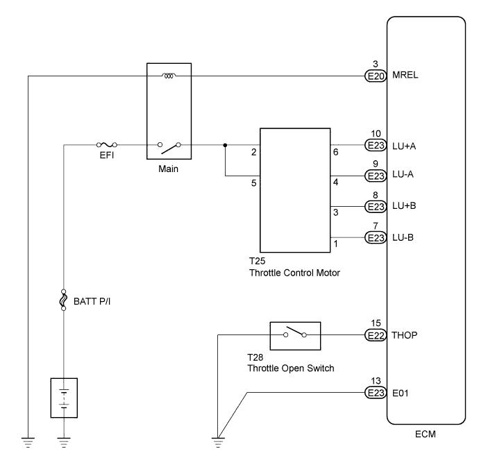
The throttle control motor is operated by the ECM and it opens and closes the throttle valve.
The fully open position of the throttle valve is detected by the throttle open switch mounted on the venturi.
If this DTC is stored, the ECM shuts down the power for the throttle control motor.
| DTC No. | DTC Detection Condition | Trouble Area |
|---|---|---|
| 15 (4) | Open or short in throttle control motor circuit |
|
| Open or short in throttle open switch circuit |
WIRING DIAGRAM
INSPECTION PROCEDURE
Tech Tips
Read freeze frame data using the intelligent tester. The ECM records vehicle and driving condition information as freeze frame data the moment a DTC is stored. When troubleshooting, freeze frame data can be helpful in determining whether the vehicle was running or stopped, whether the engine was warmed up or not, whether the air-fuel ratio was lean or rich, as well as other data recorded at the time of a malfunction.
PROCEDURE
-
INSPECT THROTTLE OPEN SWITCH
-
Disconnect the throttle open switch connector.
-
Remove the venturi.
-
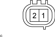
Measure the resistance of the throttle open switch.
Standard resistance Tester Connection Throttle Valve Condition Specified Condition 1 - 2 Open Below 1 Ω 1 - 2 Closed 10 kΩ or higher Tech Tips
The throttle open switch is integrated with the venturi. If the throttle open switch needs to be replaced, the entire venturi must be replaced.
NG 
REPLACE VENTURI
OK 
-
-
CHECK WIRE HARNESS (THROTTLE OPEN SWITCH - ECM AND BODY GROUND)
-
Disconnect the T28 throttle open switch connector.
-
Disconnect the E22 ECM connector.
-
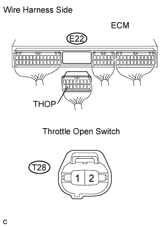
Measure the resistance of the wire harness side connectors.
Standard resistance Tester Connection Specified Condition T28-1 - Body ground Below 1 Ω E22-15 (THOP) - T28-2 Below 1 Ω E22-15 (THOP) - Body ground 10 kΩ or higher
NG
REPAIR OR REPLACE HARNESS AND CONNECTOR
OK
-
-
CHECK ECM (THROTTLE CONTROL MOTOR CIRCUIT)
-
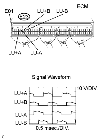
During engine racing, measure the waveform according to the value(s) in the table below.
OK Tester Connection Specified Condition E23-10 (LU+A) - E23-13 (E01) Correct waveform is as shown E23-9 (LU-A) - E23-13 (E01) Correct waveform is as shown E23-8 (LU+B) - E23-13 (E01) Correct waveform is as shown E23-7 (LU-B) - E23-13 (E01) Correct waveform is as shown
OK
REPLACE ECM
NG
-
-
INSPECT THROTTLE CONTROL MOTOR
-
Disconnect the throttle control motor connector.
-
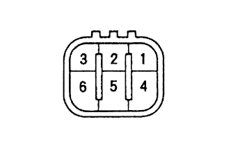
Measure the resistance of the throttle control motor.
Standard resistance Tester Connection Condition Specified Condition 1 - 2 20°C (68°F) 18 to 22 Ω 2 - 3 20°C (68°F) 18 to 22 Ω 4 - 5 20°C (68°F) 18 to 22 Ω 5 - 6 20°C (68°F) 18 to 22 Ω Tech Tips
The throttle control motor is integrated with the venturi. If the throttle control motor needs to be replaced, the entire venturi must be replaced.
NG
REPLACE VENTURI
OK
-
-
CHECK WIRE HARNESS (THROTTLE CONTROL MOTOR - ECM)
-
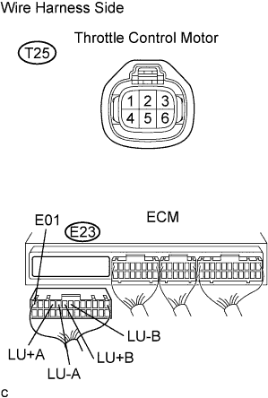
Disconnect the throttle control motor connector.
-
Disconnect the E23 ECM connector.
-
Measure the resistance of the wire harness side connectors.
Standard resistance Tester Connection Specified Condition T25-6 - E23-10 (LU+A) Below 1 Ω T25-4 - E23-9 (LU-A) Below 1 Ω T25-3 - E23-8 (LU+B) Below 1 Ω T25-1 - E23-7 (LU-B) Below 1 Ω E23-10 (LU+A) - E23-13 (E01) 10 kΩ or higher E23-9 (LU-A) - E23-13 (E01) 10 kΩ or higher E23-8 (LU+B) - E23-13 (E01) 10 kΩ or higher E23-7 (LU-B) - E23-13 (E01) 10 kΩ or higher
NG
REPAIR OR REPLACE HARNESS AND CONNECTOR
OK 
CHECK ECM POWER SOURCE CIRCUIT
-