ANTI-LOCK BRAKE SYSTEM TERMINALS OF ECU
-
TERMINALS OF ECU
Text in Illustration *a Component without harness connected
(Skid Control ECU (Brake Actuator Assembly))
- - Terminal No. (Symbol) Terminal Description 1 (+BS) Power supply for solenoid 2 (GND) Skid control ECU ground 5 (CANL) CAN communication line L 6 (CANH) CAN communication line H 8 (FL-) Front left wheel speed sensor output 9 (FL+) Front left wheel speed sensor input 10 (STP) Stop light switch input 11 (RL+) Rear left wheel speed sensor input 12 (RL-) Rear left wheel speed sensor output 15 (TS) Sensor check switch input 16 (TC) Diagnosis switch input 18 (PKB) Parking brake switch input 20 (N)* N shift position switch signal 22 (P)* P shift position switch signal 23 (+BM) Power supply for motor 24 (GND) Skid control ECU ground 25 (IG1) ECU power supply 26 (SP1) Speed signal output for speedometer 30 (FR-) Front right wheel speed sensor output 31 (FR+) Front right wheel speed sensor input 33 (RR+) Rear right wheel speed sensor input 34 (RR-) Rear right wheel speed sensor output
-
*: for Automatic Transmission
-
-
TERMINAL INSPECTION
-
Disconnect the B19 connector and measure the voltage or resistance on the wire harness side.
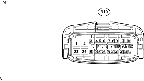
Text in Illustration *a Front view of wire harness connector
(to Skid Control ECU (Brake Actuator Assembly))
- - Tech Tips
Voltage cannot be measured with the connector connected to the skid control (brake actuator assembly) as the connector is watertight.
Terminal No. (Symbol) Wiring Color Terminal Description Condition Specified Condition B19-1 (+BS) - Body ground W-R - Body ground Power supply for solenoid (Front battery) Always 11 to 14 V B19-2 (GND) - Body ground W-B - Body ground Skid control ECU ground Always Below 1 Ω B19-10 (STP) - Body ground G - Body ground Stop light switch input Stop light switch on → off (Brake pedal depressed → released) 8 to 14 V → Below 1.5 V B19-18 (PKB) - Body ground B - Body ground Parking brake switch input Ignition switch ON, parking brake switch on → off Below 1 V → 11 to 14 V B19-23 (+BM) - Body ground W - Body ground Power supply for motor (Front battery) Always 11 to 14 V B19-24 (GND) - Body ground W-B - Body ground Skid control ECU ground Always Below 1 Ω B19-25 (IG1) - Body ground B - Body ground ECU power supply Ignition switch off → ON Below 1 V → 11 to 14 V B19-26 (SP1) - Body ground P - Body ground Speed signal output for speedometer Ignition switch ON 11 to 14 V
-