MULTI-MODE MANUAL TRANSAXLE SYSTEM Shift Paddle Switch Circuit
| DTC Code | DTC Name |
|---|---|
| Shift Paddle Switch Circuit |
DESCRIPTION
Moving the shift lever to M or E enables the gear selection. The driver can select gears optionally by operating the "+" or "-" shift paddle switch.
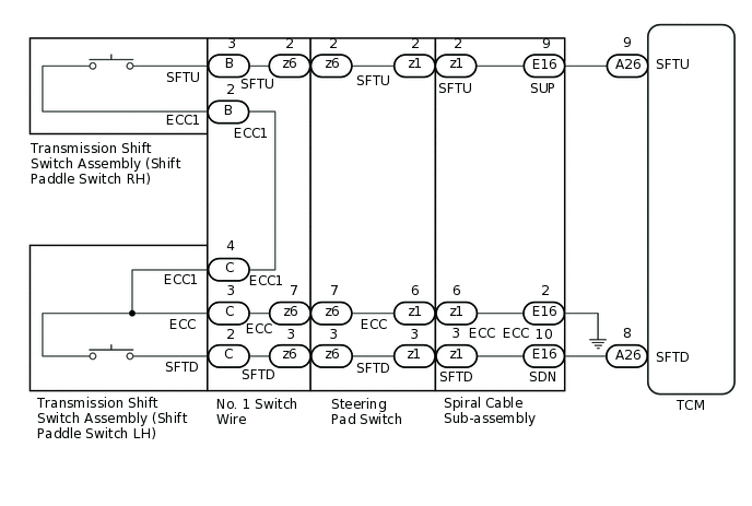
WIRING DIAGRAM
PROCEDURE
CHECK DTC OUTPUT
Result
Result
Proceed to
DTCs are not output
A
DTCs are output
B
READ VALUE USING GTS (SPORT SHIFT UP SW / SPORT SHIFT DOWN SW)
Connect the GTS to the DLC3.
Turn the ignition switch to ON.
Turn the GTS on.
Enter the following menus: Powertrain / Multi-Mode M/T / Data List / Steering Switch Signal Up and Steering SW Signal Down.
Read the Data List according to the display on the GTS.
Powertrain > Multi-Mode M/T > Data List
Tester Display
Measurement Item
Range
Normal Condition
Diagnostic Note
Steering Switch Signal Up
Steering SW Signal UP
ON or OFF
OFF: "+" (up shift) released
ON: "+" (up shift) pulled continuously
-
Steering SW Signal Down
Steering switch signal DOWN
ON or OFF
OFF: "-" (down shift) released
ON: "-" (down shift) pulled continuously
-
Powertrain > Multi-Mode M/T > Data List
Tester Display
Steering Switch Signal Up
Steering SW Signal Down
Result
Result
Proceed to
Data display is within Normal Condition range
A
Data display is not within Normal Condition range
B
CHECK HARNESS AND CONNECTOR (TCM - SHIFT PADDLE SWITCH)
-
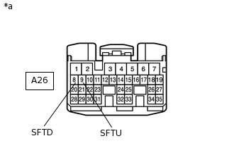
*a
Front view of wire harness connector
(to TCM)
Disconnect the TCM connector.
Measure the resistance according to the value(s) in the table below.
Standard Resistance
Tester Connection
Condition
Specified Condition
A26-9 (SFTU) - Body ground
"+" (up shift) pulled continuously
Below 2.5 Ω
"+" (up shift) released
1 MΩ or higher
A26-8 (SFTD) - Body ground
"-" (down shift) pulled continuously
Below 2.5 Ω
"-" (down shift) released
1 MΩ or higher
Result
Proceed to
OK
NG
-
CHECK HARNESS AND CONNECTOR (SPIRAL CABLE SUB-ASSEMBLY - BODY GROUND)
Disconnect the negative (-) terminal cable from the battery.
Wait for at least 90 seconds.
Remove the steering wheel assembly.
Remove the steering column cover.
Disconnect the spiral cable sub-assembly connector.
Measure the resistance according to the value(s) in the table below.
Standard Resistance
Tester Connection
Condition
Specified Condition
E16-2 (ECC) - Body ground
Always
Below 1 Ω
Result
Proceed to
OK
NG
NG REPAIR OR REPLACE HARNESS OR CONNECTOR
CHECK HARNESS AND CONNECTOR (SPIRAL CABLE SUB-ASSEMBLY - TCM)
Disconnect the TCM connector.
Disconnect the spiral cable sub-assembly connector.
Measure the resistance according to the value(s) in the table below.
Standard Resistance
Tester Connection
Condition
Specified Condition
E16-10 (SDN) - A26-8 (SFTD)
Always
Below 1 Ω
E16-10 (SDN) - Body ground
Always
10 kΩ or higher
E16-9 (SUP) - A26-9 (SFTU)
Always
Below 1 Ω
E16-9 (SUP) - Body ground
Always
10 kΩ or higher
Connect the TCM connector.
Connect the spiral cable sub-assembly connector.
Result
Proceed to
OK
NG
NG REPAIR OR REPLACE HARNESS OR CONNECTOR
CHECK HARNESS AND CONNECTOR (SPIRAL CABLE - SHIFT PADDLE SWITCH)
Disconnect the steering pad switch connector from the spiral cable sub-assembly.
-
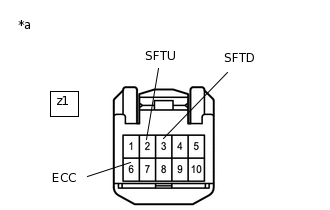
*a
Front view of wire harness connector
(to Spiral Cable Sub-assembly)
Measure the resistance according to the value(s) in the table below.
Standard Resistance
Tester Connection
Condition
Specified Condition
z1-2 (SFTU) - z1-6 (ECC)
"+" (up shift) pulled continuously
Below 1 Ω
"+" (up shift) released
10 kΩ or higher
z1-3 (SFTD) - z1-6 (ECC)
"-" (down shift) pulled continuously
Below 1 Ω
"-" (down shift) released
10 kΩ or higher
Result
Proceed to
OK
NG
NG INSPECT TRANSMISSION SHIFT SWITCH ASSEMBLY (SHIFT PADDLE SWITCH)Click here
INSPECT SPIRAL CABLE SUB-ASSEMBLY
Inspect the spiral cable sub-assembly.
Result
Proceed to
OK
NG
INSPECT TRANSMISSION SHIFT SWITCH ASSEMBLY (SHIFT PADDLE SWITCH)
Disconnect the connector from the transmission shift switch LH and RH.
Transmission Shift Switch RH ("+" Shift Paddle Switch):
-
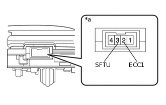
*a
Component without harness connected
(Transmission Shift Switch (Shift Paddle Switch RH))
Measure the resistance according to the value(s) in the table below.
Standard Resistance
Tester Connection
Condition
Specified Condition
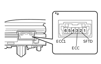
3 (SFTU) - 2 (ECC1)
"+" (up shift) pulled continuously
Below 2.5 Ω
"+" (up shift) released
1 MΩ or higher
-
-
*a
Component without harness connected
(Transmission Shift Switch (Shift Paddle Switch LH))
Transmission Shift Switch LH ("-" Shift Paddle Switch):
Measure the resistance according to the value(s) in the table below.
Standard Resistance
Tester Connection
Condition
Specified Condition
2 (SFTD) - 3 (ECC)
"-" (down shift) pulled continuously
Below 2.5 Ω
"-" (down shift) released
1 MΩ or higher
3 (ECC) - 4 (ECC1)
Always
Below 1 Ω
Result
Proceed to
OK
NG
INSPECT NO. 1 SWITCH WIRE
-
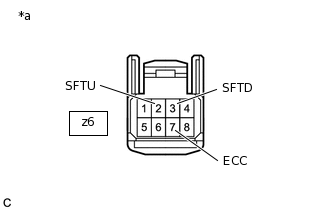
*a
Front view of wire harness connector
(to Steering Pad Switch)
Connect the transmission shift switch LH and RH connectors.
Remove the steering pad.
Disconnect the No. 1 switch wire from steering pad switch connector.
Measure the resistance according to the value(s) in the table below.
Standard Resistance
Tester Connection
Condition
Specified Condition
z6-2 (SFTU) - z6-7 (ECC)
"+" (up shift) pulled continuously
Below 2.5 Ω
"+" (up shift) released
1 MΩ or higher
z6-3 (SFTD) - z6-7 (ECC)
"-" (down shift) pulled continuously
Below 2.5 Ω
"-" (down shift) released
1 MΩ or higher
Result
Proceed to
OK
NG
NG REPLACE NO. 1 SWITCH WIRE
-