WIPER AND WASHER SYSTEM TERMINALS OF ECU
-
CHECK WINDSHIELD WIPER MOTOR ASSEMBLY
-
Disconnect the i1 windshield wiper motor assembly connector.

-
Measure the voltage and resistance on the wire harness side connector according to the value(s) in the table below.
Terminal No.
(Symbol)
Wiring Color Terminal Description Condition Specified Condition i1-3 (L) - Body ground B - Body ground Engine switch on (IG) signal (Power source circuit) Engine switch on (IG) 11 to 14 V Engine switch off Below 1 V i1-4 (+S) - Body ground W-B - Body ground Ground Always Below 1 Ω -
Reconnect the i1 windshield wiper motor assembly connector.
-
Measure the voltage and resistance on the wire harness side connector according to the value(s) in the table below.
Terminal No.
(Symbol)
Wiring Color Terminal Description Condition Specified Condition i1-1 (2S) - Body ground B - Body ground Windshield wiper motor assembly HI operation signal Windshield wiper motor assembly not operating 11 to 14 V Windshield wiper motor assembly operating in HI Below 1 V i1-2 (MPX1) - Body ground GR - Body ground LIN communication signal Engine switch on (IG) Pulse generation
Tech Tips
If the result is not as specified, there may be a malfunction in the wire harness.
-
-
CHECK HEADLIGHT ECU SUB-ASSEMBLY RH (for Triple Beam Headlight)
-
Measure the voltage according to the value(s) in the table below.
Terminal No.
(Symbol)
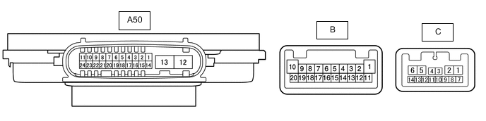
Wiring Color Terminal Description Condition Specified Condition A50-7 (HLC) - Body ground B - Body ground Headlight cleaner motor and pump assembly operation signal Engine switch on (IG), headlight cleaner motor and pump assembly not operating 11 to 14 V Engine switch on (IG), headlight cleaner motor and pump assembly operating Below 1 V A50-18 (FRWA) - Body ground B - Body ground Front washer switch operation signal Engine switch on (IG), front washer switch off 11 to 14 V Engine switch on (IG), front washer switch on Below 1 V Tech Tips
Since the A50 headlight ECU sub-assembly RH connector is a waterproof type connector, the voltage and pulses cannot be checked directly. The values listed are for reference only.
-
-
CHECK HEADLIGHT ECU SUB-ASSEMBLY RH (for Single Beam Headlight)
-
Measure the voltage according to the value(s) in the table below.
Terminal No.
(Symbol)
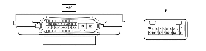
Wiring Color Terminal Description Condition Specified Condition A50-7 (HLC) - Body ground B - Body ground Headlight cleaner motor and pump assembly operation signal Engine switch on (IG), headlight cleaner motor and pump assembly not operating 11 to 14 V Engine switch on (IG), headlight cleaner motor and pump assembly operating Below 1 V A50-18 (FRWA) - Body ground B - Body ground Front washer switch operation signal Engine switch on (IG), front washer switch off 11 to 14 V Engine switch on (IG), front washer switch on Below 1 V Tech Tips
Since the A50 headlight ECU sub-assembly RH connector is a waterproof type connector, the voltage cannot be measured and pulses cannot be checked for directly. The values listed are for reference only.
-