FUEL INJECTOR INSPECTION
PROCEDURE
INSPECT FUEL INJECTOR ASSEMBLY
-
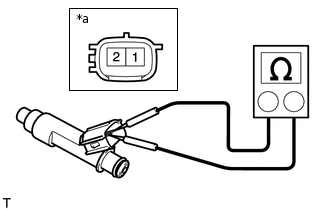
*a
Component without harness connected
(Fuel Injector Assembly)
Measure the resistance according to the value(s) in the table below.
Standard Resistance
Tester Connection
Condition
Specified Condition
1 - 2
20°C (68°F)
12.0 Ω
If the result is not as specified, replace the fuel injector assembly.
Inspect the fuel injector assembly injection.
CAUTION:Keep the fuel injector assembly away from sparks during the test.
-
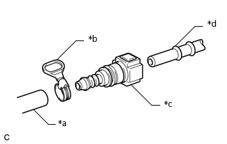
*a
SST (Hose)
*b
SST (Hose Band)
*c
SST (Fuel Tube Connector)
*d
Fuel Pipe (Vehicle Side)
Connect SST (fuel tube connector) to SST (hose) with SST (hose band), and then connect them to the fuel pipe (vehicle side).
09268-31014
09268-41500
09268-41700
95336-08070
Apply a light coat of gasoline to a new O-ring. Then install the O-ring onto the fuel injector assembly.
-
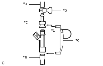
*1
O-ring
*a
SST (Hose)
*b
SST (Hose Band)
*c
SST (Adapter)
*d
SST (Clamp)
*e
Vinyl Tube
Connect SST (adapter) and SST (hose) to the fuel injector assembly, and hold them with SST (clamp).
09268-31014
09268-41141
09268-41410
09268-41700
95336-08070
-
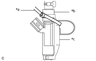
*a
SST (Tie Band)
*b
SST (Adapter)
*c
SST (Clamp)
Tie SST (clamp) and SST (adapter) together with SST (tie band) as shown in the illustration.
09268-31014
09268-41410
09268-41141
09268-41800
Install a vinyl tube onto the fuel injector assembly.
CAUTION:Install a suitable vinyl tube onto the fuel injector assembly to prevent fuel from spraying.
Set the fuel injector assembly in a graduated cylinder.
Operate the fuel pump.
-
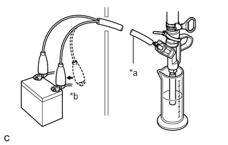
*a
SST (Wire)
*b
Connect
Connect SST (wire) to the fuel injector assembly and battery for 15 seconds, and measure the injection volume with the graduated cylinder. Test each fuel injector assembly 2 or 3 times.
09842-30080
Note:Always switch the voltage on and off at the battery side, not the fuel injector assembly side.
Standard Injection Volume
Battery Connection
Condition
Specified Condition
Positive (+) battery terminal - Negative (-) battery terminal
Per 15 seconds
47 to 57 cc (2.9 to 3.5 cu. in.)
Difference between Each Fuel Injector Assembly
10 cc (0.6 cu. in.) or less
If the result is not as specified, replace the fuel injector assembly.
-
Check for fuel drop.
In the condition above, disconnect SST (wire) from the battery and check for fuel drop from the fuel injector assembly.
Standard Fuel Drop
1 drop or less per 51 minutes
If the result is not as specified, replace the fuel injector assembly.
-