CYLINDER HEAD GASKET INSTALLATION
CAUTION / NOTICE / HINT
PROCEDURE
INSTALL CYLINDER HEAD GASKET
-
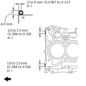
*1
Cylinder Block Sub-assembly

Engine Front
Apply seal packing (Diameter 4.0 mm (0.157 in.)) to the cylinder block sub-assembly as shown in the illustration.
Seal packing
Toyota Genuine Seal Packing Black, Three Bond 1207B or equivalent
Note:Remove any oil from the cylinder block sub-assembly.
-
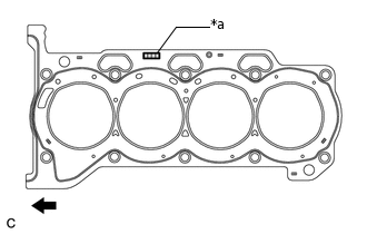
*a
Lot No.
Engine Front
Place a new cylinder head gasket on the cylinder block sub-assembly with the Lot No. stamp facing upward.
Note:Install the cylinder head gasket within 3 minutes of applying seal packing.
-
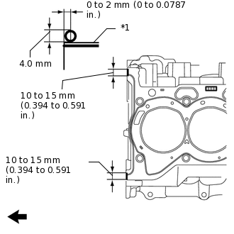
*1
Cylinder Head Gasket
Engine Front
Apply seal packing (Diameter 4.0 mm (0.157 in.)) to the new cylinder head gasket as shown in the illustration.
Seal packing
Toyota Genuine Seal Packing Black, Three Bond 1207B or equivalent
Note:Remove any oil from the cylinder head gasket and cylinder head sub-assembly.
Install the cylinder head gasket within 3 minutes and tighten the bolts within 15 minutes of applying seal packing.
-
INSTALL CYLINDER HEAD SUB-ASSEMBLY
Tip:The cylinder head set bolts are tightened in 2 progressive steps.
Apply a light coat of engine oil to the bolt threads and the area beneath the bolt heads that come in contact with the plate washers.
Place the cylinder head sub-assembly on the cylinder block sub-assembly, and set the cylinder head set bolts and plate washers to the cylinder head sub-assembly.
Note:Do not drop the plate washers into the cylinder head sub-assembly.
-
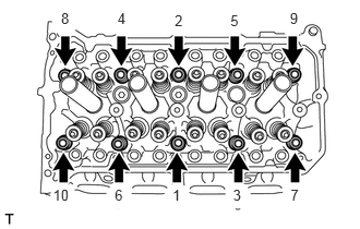
Using a 10 mm bi-hexagon wrench, uniformly install and tighten the 10 cylinder head set bolts and 10 plate washers in several steps and in the order shown in the illustration.
49 N*m
500 kgf*cm
36 ft.*lbf
-
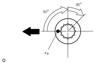
*a
Paint Mark
Engine Front
Mark the front side of each cylinder head set bolt with paint.
Tighten the cylinder head set bolts an additional 90° and then another 45° as shown in the illustration.
Check that the paint mark is now at a 135° angle to the front.
-
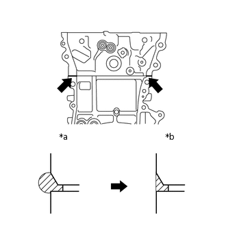
*a
Before wiping off
*b
After wiping off
Wipe off any seal packing seeped out from the contact surfaces between the cylinder head sub-assembly and cylinder block sub-assembly.
INSTALL VALVE LASH ADJUSTER ASSEMBLY
INSTALL NO. 1 VALVE ROCKER ARM SUB-ASSEMBLY
INSTALL NO. 1 CAMSHAFT BEARING
INSTALL NO. 2 CAMSHAFT BEARING
INSTALL NO. 2 CAMSHAFT
Clean the camshaft journals.
Apply a light coat of engine oil to the camshaft journals, camshaft housing sub-assembly and camshaft bearing caps.
-
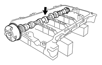
Install the No. 2 camshaft to the camshaft housing sub-assembly.
INSTALL CAMSHAFT
Clean the camshaft journals.
Apply a light coat of engine oil to the camshaft journals and camshaft housing sub-assembly.
-
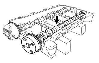
Install the camshaft to the camshaft housing sub-assembly.
INSTALL CAMSHAFT BEARING CAP
INSTALL CAMSHAFT HOUSING SUB-ASSEMBLY
INSTALL CHAIN SUB-ASSEMBLY