VALVE CLEARANCE(w/o Glow Plug Controller) ADJUSTMENT
PROCEDURE
PRECAUTION
Note:After turning the ignition switch off, waiting time may be required before disconnecting the cable from the negative (-) battery terminal. Therefore, make sure to read the disconnecting the cable from the negative (-) battery terminal notices before proceeding with work.
DISCONNECT CABLE FROM NEGATIVE BATTERY TERMINAL
Note:When disconnecting the cable, some systems need to be initialized after the cable is reconnected.
REMOVE FRONT WHEEL RH
REMOVE NO. 1 ENGINE UNDER COVER (for Half Cover Type)
REMOVE NO. 1 ENGINE UNDER COVER (for Full Cover Type)
REMOVE REAR ENGINE UNDER COVER RH
REMOVE NO. 1 ENGINE COVER (w/ No. 1 Engine Cover)
DISCONNECT ENGINE WIRE
Disconnect the engine wire.
REMOVE VACUUM PUMP ASSEMBLY
REMOVE HARNESS BRACKET
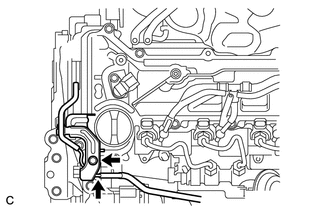
DISCONNECT SENSOR BRACKET
-
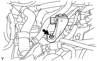
Remove the nut and disconnect the sensor bracket.
-
REMOVE VENTILATION HOSE
-
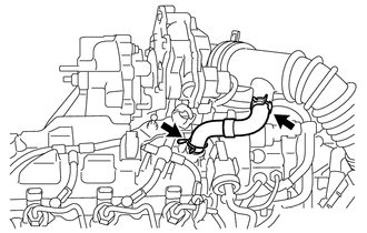
Slide the 2 clips and remove the ventilation hose.
-
REMOVE NO. 2 CYLINDER HEAD COVER
-
Remove the 3 fuel pipe clamps.
-
Separate the fuel check valve from the No. 2 cylinder head cover.
Remove the No. 2 cylinder head cover.
-
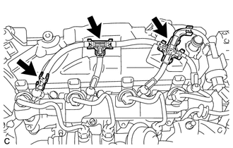
REMOVE HARNESS BRACKET
-
Disconnect the vacuum hose.
Remove the bolt and harness bracket.
-
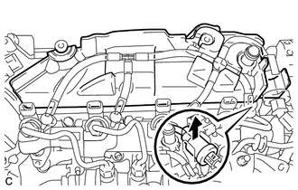
REMOVE CYLINDER HEAD COVER SUB-ASSEMBLY
-
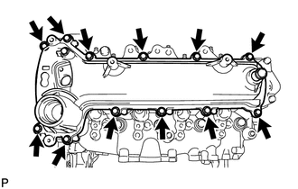
Remove the 12 bolts and cylinder head cover sub-assembly.
-
CHECK VALVE CLEARANCE
Set the No. 1 cylinder to TDC/Compression.
-
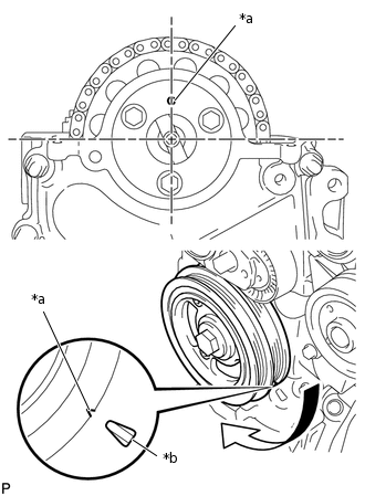
*a
Timing Mark
*b
TDC Mark
Turn the crankshaft damper sub-assembly until the grooves of the crankshaft damper sub-assembly and timing chain cover sub-assembly are aligned.
Check that the timing mark of the camshaft timing sprocket is in the position shown in the illustration.
Tip:If not, turn the crankshaft damper 1 revolution (360°) to align the timing mark and camshaft timing sprocket as above.
-
Check the valve clearance of the No. 1 cylinder exhaust valve and the No. 2 cylinder intake valve.
-
*1
Camshaft
*2
No. 1 Valve Rocker Arm Sub-assembly
*a
View A
*b
for No. 1 Cylinder Exhaust Valve
*c
for No. 2 Cylinder Intake Valve
*d
Feeler Gauge
Using a feeler gauge, measure the clearance between the camshaft and No. 1 valve rocker arm sub-assembly as shown in the illustration.
Standard Valve Clearance (cold)
Intake
0.11 to 0.17 mm (0.00433 to 0.00669 in.)
Exhaust
0.14 to 0.20 mm (0.00551 to 0.00787 in.)
Note:Insert the feeler gauge with its center aligned with the center of the roller and parallel to the No. 1 valve rocker arm sub-assembly.
Do not apply excessive force to the valve adjusting screw when using adjusting tools such as SST and a screwdriver.
Tip:If the clearance is not as specified, record the measurements, and then adjust the valve clearance.
-
Check the valve clearance of the No. 1 cylinder intake valve and the No. 3 cylinder exhaust valve.
Turn the crankshaft 180° clockwise.
-
*1
Camshaft
*2
No. 1 Valve Rocker Arm Sub-assembly
*a
View A
*b
for No. 1 Cylinder Intake Valve
*c
for No. 3 Cylinder Exhaust Valve
*d
Feeler Gauge
Using a feeler gauge, measure the clearance between the camshaft and No. 1 valve rocker arm sub-assembly as shown in the illustration.
Standard Valve Clearance (cold)
Intake
0.11 to 0.17 mm (0.00433 to 0.00669 in.)
Exhaust
0.14 to 0.20 mm (0.00551 to 0.00787 in.)
Note:Insert the feeler gauge with its center aligned with the center of the roller and parallel to the No. 1 valve rocker arm sub-assembly.
Do not apply excessive force to the valve adjusting screw with adjusting tools when measuring or adjusting.
Tip:If the clearance is not as specified, record the measurements, and then adjust the valve clearance.
Check the valve clearance of the No. 3 cylinder intake valve and No. 4 cylinder exhaust valve.
Turn the crankshaft 180° clockwise.
-
*1
Camshaft
*2
No. 1 Valve Rocker Arm Sub-assembly
*a
View A
*b
for No. 3 Cylinder Intake Valve
*c
for No. 4 Cylinder Exhaust Valve
*d
Feeler Gauge
Using a feeler gauge, measure the clearance between the camshaft and No. 1 valve rocker arm sub-assembly as shown in the illustration.
Standard Valve Clearance (cold)
Intake
0.11 to 0.17 mm (0.00433 to 0.00669 in.)
Exhaust
0.14 to 0.20 mm (0.00551 to 0.00787 in.)
Note:Insert the feeler gauge with its center aligned with the center of the roller and parallel to the No. 1 valve rocker arm sub-assembly.
Do not apply excessive force to the valve adjusting screw with adjusting tools when measuring or adjusting.
Tip:If the clearance is not as specified, record the measurements, and then adjust the valve clearance.
Check the valve clearance of the No. 2 cylinder exhaust valve and No. 4 cylinder intake valve.
Turn the crankshaft 180° clockwise.
-
*1
Camshaft
*2
No. 1 Valve Rocker Arm Sub-assembly
*a
View A
*b
for No. 2 Cylinder Exhaust Valve
*c
for No. 4 Cylinder Intake Valve
*d
Feeler Gauge
Using a feeler gauge, measure the clearance between the camshaft and No. 1 valve rocker arm sub-assembly as shown in the illustration.
Standard Valve Clearance (cold)
Intake
0.11 to 0.17 mm (0.00433 to 0.00669 in.)
Exhaust
0.14 to 0.20 mm (0.00551 to 0.00787 in.)
Note:Insert the feeler gauge with its center aligned with the center of the roller and parallel to the No. 1 valve rocker arm sub-assembly.
Do not apply excessive force to the valve adjusting screw with adjusting tools when measuring or adjusting.
Tip:If the clearance is not as specified, record the measurements, and then adjust the valve clearance.
ADJUST VALVE CLEARANCE
-
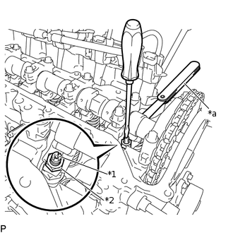
*1
Valve Adjusting Screw
*2
Valve Adjusting Nut
Using SST and a screwdriver, loosen the valve adjusting nut while keeping the valve adjusting screw in position.
09248-56010
-
*1
Valve Adjusting Screw
*2
Valve Adjusting Nut
*a
Feeler Gauge
Adjust valve clearance (intake side).
Insert a feeler gauge (0.14 mm (0.00551 in.)) between the camshaft and No. 1 valve rocker arm sub-assembly, and turn the valve adjusting screw to adjust it.
Valve Clearance (cold)
0.14 mm (0.00551 in.)
-
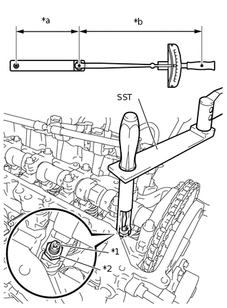
*1
Valve Adjusting Screw
*2
Valve Adjusting Nut
*a
Length of SST 150 mm (5.91 in.)
*b
Length of Torque Wrench 300 mm (11.81 in.)
Using SST and a screwdriver, tighten the valve adjusting nut while keeping the valve adjusting screw in position.
09248-56010
without SST [Torque (N*m(kgf*cm, ft.*lbf))]
20 N*m
204 kgf*cm
15 ft.*lbf
with SST [Reading of Torque wrench (N*m(kgf*cm, ft.*lbf))]
13 N*m
133 kgf*cm
10 ft.*lbf
Tip:This torque value is effective when SST is parallel to the torque wrench.
The "with SST" torque value is effective when using SST with a fulcrum length of 150 mm (5.91 in.).
The "with SST" torque value is effective when using a torque wrench with a fulcrum length of 300 mm (11.81 in.).
If using a torque wrench with a different length, or connecting the torque wrench and SST at an angle, refer to the alternate torque values.
Adjust the valve clearance (exhaust side).
Valve Clearance (cold)
0.17 mm (0.00669 in.)
Tip:Perform the same procedure as for the intake side valve clearance adjustment.
-
INSTALL CYLINDER HEAD COVER SUB-ASSEMBLY
-

Seal Packing
Apply seal packing to the 4 locations as shown in the illustration, and then install the cylinder head cover sub-assembly.
Seal packing
Toyota Genuine Seal Packing Black, Three Bond 1207B or equivalent
Note:Remove any oil from the contact surface.
Install the cylinder head cover within 3 minutes and tighten the bolts within 15 minutes of applying the seal packing.
Do not start the engine for at least 2 hours after installing the cylinder head cover sub-assembly.
-
Temporarily install the cylinder head cover sub-assembly with the 12 bolts.
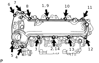
Fully tighten the 12 bolts in the order shown in the illustration.
11 N*m
112 kgf*cm
8 ft.*lbf
-
INSTALL HARNESS BRACKET
Install the harness bracket with the bolt.
8.0 N*m
82 kgf*cm
71 in.*lbf
Connect the vacuum hose.
INSTALL NO. 2 CYLINDER HEAD COVER
-

Install the No. 2 cylinder head cover.
Install the fuel check valve to the No. 2 cylinder head cover.
Install the 3 fuel pipe clamps.
-
INSTALL SENSOR BRACKET
Install the sensor bracket with the nut.
8.0 N*m
82 kgf*cm
71 in.*lbf
INSTALL HARNESS BRACKET
INSTALL VENTILATION HOSE
Install the ventilation hose and slide the 2 clips to secure it.
INSTALL VACUUM PUMP ASSEMBLY
CONNECT ENGINE WIRE
Connect the engine wire.
INSTALL NO. 1 ENGINE COVER (w/ No. 1 Engine Cover)
INSTALL REAR ENGINE UNDER COVER RH
INSTALL NO. 1 ENGINE UNDER COVER (for Half Cover Type)
INSTALL NO. 1 ENGINE UNDER COVER (for Full Cover Type)
INSTALL FRONT WHEEL RH
103 N*m
1050 kgf*cm
76 ft.*lbf
CONNECT CABLE TO NEGATIVE BATTERY TERMINAL
Connect the cable to the negative (-) battery terminal.
5.4 N*m
55 kgf*cm
48 in.*lbf
Note:When disconnecting the cable, some systems need to be initialized after the cable is reconnected.