EMISSION CONTROL SYSTEM
Figure 1. EGR System (Models with EGR Cooler)
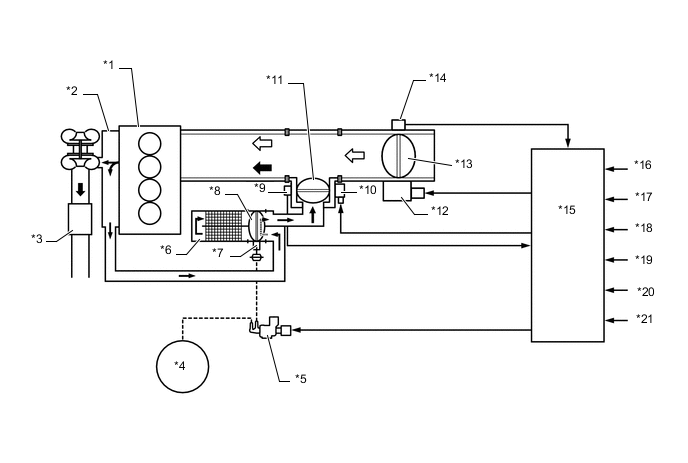
| *1 | Cylinder Block Sub-assembly | *2 | Exhaust Manifold |
| *3 | Oxidation Catalyst | *4 | Vacuum Pump |
| *5 | Vacuum Switching Valve Assembly | *6 | No. 1 EGR Cooler |
| *7 | Actuator for No. 2 EGR Valve Assembly | *8 | No. 2 EGR Valve Assembly |
| *9 | EGR Valve Position Sensor | *10 | DC Motor for EGR Valve Control |
| *11 | Electric EGR Control Valve Assembly | *12 | Throttle Motor |
| *13 | Diesel Throttle Valve | *14 | Throttle Position Sensor |
| *15 | ECM | *16 | Crank Position Sensor |
| *17 | Accelerator Pedal Sensor Assembly | *18 | Engine Coolant Temperature Sensor |
| *19 | Turbo Pressure Sensor | *20 | Inlet Air Temperature Sensor |
| *21 | Intake Mass Air Flow Meter Sub-assembly | - | - |
 |
Exhaust Gas |  |
Intake Air |
Figure 2. EGR System (Models without EGR Cooler)
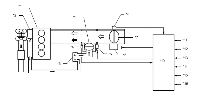
| *1 | Cylinder Block Sub-assembly | *2 | Exhaust Manifold |
| *3 | EGR Valve Adapter | *4 | EGR Valve Position Sensor |
| *5 | DC Motor for EGR Valve Control | *6 | Throttle Motor |
| *7 | Diesel Throttle Valve | *8 | Throttle Position Sensor |
| *9 | Electric EGR Control Valve Assembly | *10 | ECM |
| *11 | Crank Position Sensor | *12 | Accelerator Pedal Sensor Assembly |
| *13 | Engine Coolant Temperature Sensor | *14 | Turbo Pressure Sensor |
| *15 | Inlet Air Temperature Sensor | *16 | Intake Mass Air Flow Meter Sub-assembly |
| |
Exhaust Gas | |
Intake Air |
Figure 3. Catalyst Support Control
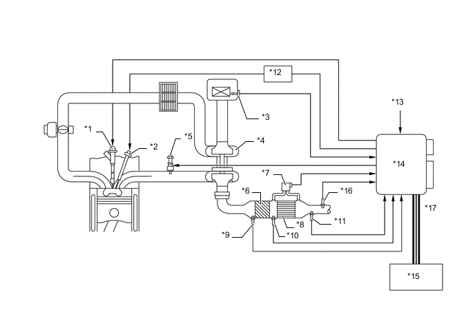
| *1 | Injector Assembly | *2 | Glow Plug Assembly |
| *3 | Intake Mass Air Flow Meter Sub-assembly | *4 | Turbocharger Sub-assembly |
| *5 | Exhaust Fuel Addition Injector Assembly | *6 | Oxidation Catalyst |
| *7 | Differential Pressure Sensor | *8 | Diesel Particulate Filter (DPF) |
| *9 | Exhaust Gas Temperature Sensor | *10 | No. 2 Exhaust Gas Temperature Sensor |
| *11 | No. 3 Exhaust Gas Temperature Sensor | *12 | Glow Plug Controller |
| *13 | Engine Coolant Temperature Sensor | *14 | ECM |
| *15 | Combination Meter Assembly | *16 | Air Fuel Ratio Sensor |
| *17 | CAN (V Bus) | - | - |
Figure 4. UREA SCR System
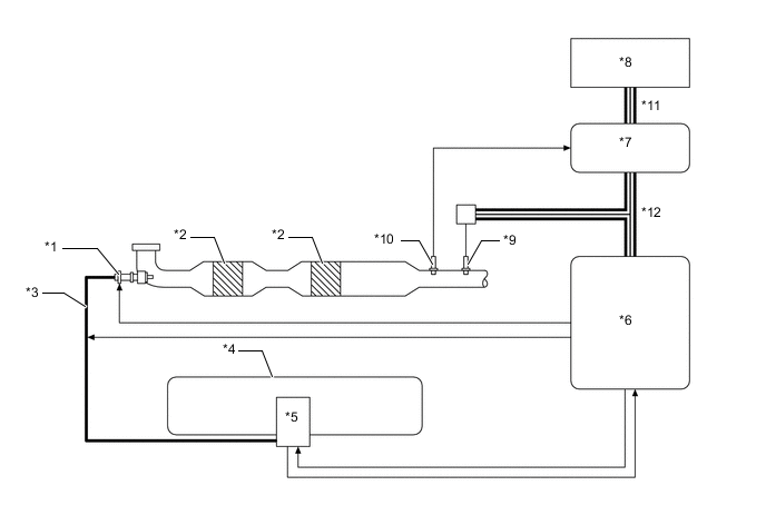
| *1 | UREA Injector Set | *2 | SCR Catalyst |
| *3 | UREA Tube with Heater Assembly | *4 | UREA Tank Sub-assembly |
| *5 | UREA Pump | *6 | UREA Pump Control ECU |
| *7 | ECM | *8 | Combination Meter Assembly |
| *9 | NOx Sensor (Nitrogen Oxides Sensor) | *10 | No. 4 Exhaust Gas Temperature Sensor |
| *11 | CAN (Local Bus) | *12 | CAN (V Bus) |