AUDIO AND VISUAL SYSTEM(w/ Navigation System), Diagnostic DTC:B15D3
| DTC Code | DTC Name |
|---|---|
| B15D3 | Stereo Component Amplifier Disconnected |
DESCRIPTION
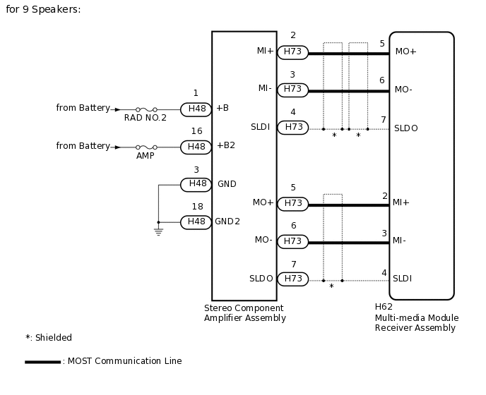
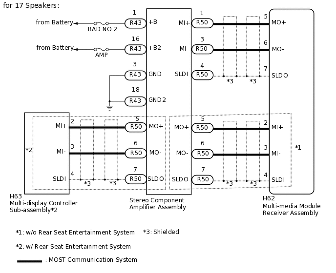
The multi-media module receiver assembly and stereo component amplifier assembly are connected by the MOST communication line.
When a MOST communication error occurs between the multi-media module receiver assembly and stereo component amplifier assembly, these DTCs will be stored.
DTC No. |
Detection Item |
DTC Detection Condition |
Trouble Area |
|---|---|---|---|
B15D3 |
Stereo Component Amplifier Disconnected |
A device that is listed in the MOST network connected device record of the master unit is missing. |
|
For the MOST network, the multi-media module receiver assembly is the master unit.
WIRING DIAGRAM
CAUTION / NOTICE / HINT
Inspect the fuses for circuits related to this system before performing the following inspection procedure.
PROCEDURE
CHECK OPTIONAL COMPONENTS (INCLUDING ASSOCIATED WIRING)
Check for optional components.
Check that optional components (including associated wiring) which generate radio waves are not installed.
Result
Result
Proceed to
Optional components (including associated wiring) are installed.
A
Optional components (including associated wiring) are not installed.
B
Tip:Electrical noise from radio waves generated by optional components or the wiring for those components may affect AVC-LAN communication.
This DTC may be stored when an AVC-LAN communication error occurs due to electrical noise.
B CLEAR DTCClick here
REMOVE OPTIONAL COMPONENTS (INCLUDING ASSOCIATED WIRING)
Remove optional components (including associated wiring).
Note:Do not remove optional components or associated wiring without the permission of the customer.
Result
Proceed to
NEXT
CLEAR DTC
Clear the DTCs.
Body Electrical > Navigation System > Clear DTCs
Result
Proceed to
NEXT
CHECK FOR DTC
Recheck for DTCs and check if the same DTC is output again.
Body Electrical > Navigation System > Trouble Codes
OK
No DTCs are output.
Result
Proceed to
OK
NG
OK END (COMMUNICATION MALFUNCTION DUE TO NOISE)
CHECK HARNESS AND CONNECTOR (STEREO COMPONENT AMPLIFIER ASSEMBLY - BATTERY AND BODY GROUND)
-
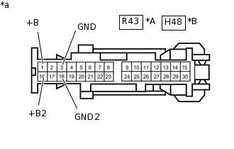
*A
for 17 Speakers
*B
for 9 Speakers
*a
Front view of wire harness connector
(to Stereo Component Amplifier Assembly)
Disconnect the stereo component amplifier assembly connector.
Measure the resistance according to the value(s) in the table below.
Standard Resistance
for 17 Speakers
Tester Connection
Condition
Specified Condition
R43-3 (GND) - Body ground
Always
Below 1 Ω
R43-18 (GND2) - Body ground
Always
Below 1 Ω
for 9 Speakers
Tester Connection
Condition
Specified Condition
H48-3 (GND) - Body ground
Always
Below 1 Ω
H48-18 (GND2) - Body ground
Always
Below 1 Ω
Measure the voltage according to the value(s) in the table below.
Standard Voltage
for 17 Speakers
Tester Connection
Condition
Specified Condition
R43-1 (+B) - R43-3 (GND)
Always
11 to 14 V
R43-16 (+B2) - R43-3 (GND)
Always
11 to 14 V
for 9 Speakers
Tester Connection
Condition
Specified Condition
H48-1 (+B) - H48-3 (GND)
Always
11 to 14 V
H48-16 (+B2) - H48-3 (GND)
Always
11 to 14 V
Result
Result
Proceed to
OK (w/o Rear Seat Entertainment System)
A
OK (w/ Rear Seat Entertainment System)
B
NG
C
B CHECK HARNESS AND CONNECTOR (STEREO COMPONENT AMPLIFIER ASSEMBLY - MULTI-MEDIA MODULE RECEIVER AND MULTI-DISPLAY CONTROLLER SUB-ASSEMBLY)Click here
C REPAIR OR REPLACE HARNESS OR CONNECTOR
-
CHECK HARNESS AND CONNECTOR (MULTI-MEDIA MODULE RECEIVER ASSEMBLY - STEREO COMPONENT AMPLIFIER ASSEMBLY)
Disconnect the H62 multi-media module receiver assembly connector.
Disconnect the R50*1 or H73*2 stereo component amplifier assembly connector.
*1: for 17 Speakers
*2: for 9 Speakers
Measure the resistance according to the value(s) in the table below.
Standard Resistance
Table 1. for 17 Speakers Tester Connection
Condition
Specified Condition
H62-2 (MI+) - R50-5 (MO+)
Always
Below 1 Ω
H62-3 (MI-) - R50-6 (MO-)
Always
Below 1 Ω
H62-4 (SLDI) - R50-7 (SLDO)
Always
Below 1 Ω
H62-5 (MO+) - R50-2 (MI+)
Always
Below 1 Ω
H62-6 (MO-) - R50-3 (MI-)
Always
Below 1 Ω
H62-7 (SLDO) - R50-4 (SLDI)
Always
Below 1 Ω
H62-2 (MI+) - Body ground
Always
10 kΩ or higher
H62-3 (MI-) - Body ground
Always
10 kΩ or higher
H62-4 (SLDI) - Body ground
Always
10 kΩ or higher
H62-5 (MO+) - Body ground
Always
10 kΩ or higher
H62-6 (MO-) - Body ground
Always
10 kΩ or higher
H62-7 (SLDO) - Body ground
Always
10 kΩ or higher
Table 2. for 9 Speakers Tester Connection
Condition
Specified Condition
H62-2 (MI+) - H73-5 (MO+)
Always
Below 1 Ω
H62-3 (MI-) - H73-6 (MO-)
Always
Below 1 Ω
H62-4 (SLDI) - H73-7 (SLDO)
Always
Below 1 Ω
H62-5 (MO+) - H73-2 (MI+)
Always
Below 1 Ω
H62-6 (MO-) - H73-3 (MI-)
Always
Below 1 Ω
H62-7 (SLDO) - H73-4 (SLDI)
Always
Below 1 Ω
H62-2 (MI+) - Body ground
Always
10 kΩ or higher
H62-3 (MI-) - Body ground
Always
10 kΩ or higher
H62-4 (SLDI) - Body ground
Always
10 kΩ or higher
H62-5 (MO+) - Body ground
Always
10 kΩ or higher
H62-6 (MO-) - Body ground
Always
10 kΩ or higher
H62-7 (SLDO) - Body ground
Always
10 kΩ or higher
Result
Proceed to
OK
NG
NG REPAIR OR REPLACE HARNESS OR CONNECTOR
REPLACE STEREO COMPONENT AMPLIFIER ASSEMBLY
Replace the stereo component amplifier assembly with a known good one.
Click here
for 17 Speakers:
for 9 Speakers:
Result
Proceed to
NEXT
CLEAR DTC
Clear the DTCs.
Body Electrical > Navigation System > Clear DTCs
Result
Proceed to
NEXT
CHECK FOR DTC
Recheck for DTCs and check if the same DTC is output again.
Body Electrical > Navigation System > Trouble Codes
OK
No DTCs are output.
Result
Proceed to
OK
NG
OK END (STEREO COMPONENT AMPLIFIER ASSEMBLY IS DEFECTIVE)
CHECK HARNESS AND CONNECTOR (STEREO COMPONENT AMPLIFIER ASSEMBLY - MULTI-MEDIA MODULE RECEIVER AND MULTI-DISPLAY CONTROLLER SUB-ASSEMBLY)
Disconnect the H62 multi-media module receiver assembly connector.
Disconnect the R50 stereo component amplifier assembly connector.
Disconnect the H63 multi-display controller sub-assembly connector.
Measure the resistance according to the value(s) in the table below.
Standard Resistance
Tester Connection
Condition
Specified Condition
H62-5 (MO+) - R50-2 (MI+)
Always
Below 1 Ω
H62-6 (MO-) - R50-3 (MI-)
Always
Below 1 Ω
H62-7 (SLDO) - R50-4 (SLDI)
Always
Below 1 Ω
R50-5 (MO+) - H63-2 (MI+)
Always
Below 1 Ω
R50-6 (MO-) - H63-3 (MI-)
Always
Below 1 Ω
R50-7 (SLDO) - H63-4 (SLDI)
Always
Below 1 Ω
R50-2 (MI+) - Body ground
Always
10 kΩ or higher
R50-3 (MI-) - Body ground
Always
10 kΩ or higher
R50-4 (SLDI) - Body ground
Always
10 kΩ or higher
R50-5 (MO+) - Body ground
Always
10 kΩ or higher
R50-6 (MO-) - Body ground
Always
10 kΩ or higher
R50-7 (SLDO) - Body ground
Always
10 kΩ or higher
Result
Proceed to
OK
NG
NG REPAIR OR REPLACE HARNESS OR CONNECTOR
REPLACE STEREO COMPONENT AMPLIFIER ASSEMBLY
Replace the stereo component amplifier assembly with a known good one.
Result
Proceed to
NEXT
CLEAR DTC
Clear the DTCs.
Body Electrical > Navigation System > Clear DTCs
Result
Proceed to
NEXT
CHECK FOR DTC
Recheck for DTCs and check if the same DTC is output again.
Body Electrical > Navigation System > Trouble Codes
OK
No DTCs are output.
Result
Proceed to
OK
NG
OK END (STEREO COMPONENT AMPLIFIER ASSEMBLY IS DEFECT)