ANTI-LOCK BRAKE SYSTEM, Diagnostic DTC:C1428
| DTC Code | DTC Name |
|---|---|
| C1428 | Motor Circuit Malfunction |
DESCRIPTION
DTC No. |
Detection Item |
DTC Detection Condition |
Trouble Area |
|---|---|---|---|
C1428 |
Motor Circuit Malfunction |
With the motor relay OFF and the motor fail safe relay ON, an open in the motor circuit continues for 2 seconds or more. |
Brake actuator assembly (Motor circuit) |
WIRING DIAGRAM
Refer to DTCs C146C and C146D.
CAUTION / NOTICE / HINT
When replacing the skid control ECU (brake actuator assembly), perform acceleration sensor zero point calibration and CVT oil pressure calibration (for continuously variable transaxle).
K111:Click here
K111F:Click here
PROCEDURE
CHECK HARNESS AND CONNECTOR (GND2 TERMINAL)
Turn the ignition switch off.
Make sure that there is no looseness at the locking part and the connecting part of the connectors.
Disconnect the A63 skid control ECU (brake actuator assembly) connector.
-
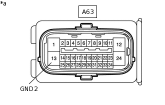
*a
Front view of wire harness connector
(to Skid Control ECU [Brake Actuator Assembly])
Measure the resistance according to the value(s) in the table below.
Standard Resistance
Tester Connection
Condition
Specified Condition
A63-13 (GND2) - Body ground
Always
Below 1 Ω
Result
Proceed to
OK
NG
NG REPAIR OR REPLACE HARNESS OR CONNECTOR (GND2 CIRCUIT)