CONDENSER(except 1AD-FTV) INSTALLATION
PROCEDURE
INSTALL CONDENSER WITH RECEIVER ASSEMBLY
-
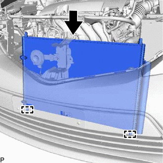
Engage the 2 guides to install the condenser with receiver assembly as shown in the illustration.
Note:Do not damage the condenser with receiver assembly or radiator when installing the condenser with receiver assembly.
Tip:If a new condenser with receiver assembly is installed, add compressor oil to the condenser with receiver assembly as follows.
Capacity
Add 40 cc (1.35 fl. oz.)
Compressor Oil
ND-OIL 8 or equivalent
-
CONNECT AIR CONDITIONER TUBE ASSEMBLY
Remove the vinyl tape from the air conditioner tube assembly and the connecting part of the condenser with receiver assembly.
Sufficiently apply compressor oil to a new O-ring and the fitting surface of the tube joint.
Compressor Oil
ND-OIL 8 or equivalent
Install the O-ring to the air conditioner tube assembly.
Install the air conditioner tube assembly to the condenser with receiver assembly with the bolt.
5.4 N*m
55 kgf*cm
48 in.*lbf
CONNECT DISCHARGE HOSE SUB-ASSEMBLY
Remove the vinyl tape from the discharge hose sub-assembly and the connecting part of the condenser with receiver assembly.
Sufficiently apply compressor oil to a new O-ring and the fitting surface of the hose joint.
Compressor Oil
ND-OIL 8 or equivalent
Install the O-ring to the discharge hose sub-assembly.
Install the discharge hose sub-assembly to the condenser with receiver assembly with the bolt.
5.4 N*m
55 kgf*cm
48 in.*lbf
INSTALL NO. 2 FAN SHROUD
Engage the 2 guides and 2 claws.
Install the No. 2 fan shroud with the 2 bolts.
7.0 N*m
71 kgf*cm
62 in.*lbf
Engage the clamp to connect the No. 3 water by-pass hose to the No. 2 fan shroud.
INSTALL NO. 1 RADIATOR SUPPORT (for 1ND-TV)
INSTALL UPPER RADIATOR SUPPORT SUB-ASSEMBLY (for 1ND-TV)
INSTALL UPPER RADIATOR SUPPORT SUB-ASSEMBLY (for 1NR-FE)
INSTALL UPPER RADIATOR SUPPORT SUB-ASSEMBLY (for 1ZR-FAE)
CONNECT NO. 1 WATER HOSE CLAMP BRACKET (for 1ND-TV)
CONNECT NO. 1 WATER HOSE CLAMP BRACKET (for 1NR-FE)
CONNECT NO. 1 WATER HOSE CLAMP BRACKET (for 1ZR-FAE)
INSTALL BATTERY CLAMP SUB-ASSEMBLY
Install the battery clamp sub-assembly and battery clamp bolt with the bolt and nut.
Bolt
16.5 N*m
168 kgf*cm
12 ft.*lbf
Nut
3.5 N*m
36 kgf*cm
31 in.*lbf
INSTALL HEADLIGHT ASSEMBLY LH (for 1ND-TV)
INSTALL HEADLIGHT ASSEMBLY RH (for 1ND-TV)
Tip:Use the same procedure as for the LH side.
INSTALL RADIATOR GRILLE SUB-ASSEMBLY
ADJUST HOOD SUB-ASSEMBLY
CHARGE AIR CONDITIONING SYSTEM WITH REFRIGERANT
WARM UP ENGINE
INSPECT FOR REFRIGERANT LEAK