AUDIO AND VISUAL SYSTEM(w/ Navigation System), Diagnostic DTC:B15C3
| DTC Code | DTC Name |
|---|---|
| B15C3 | Speaker Output Short |
DESCRIPTION
This DTC is stored when a malfunction occurs in the speakers.
DTC No. |
Detection Item |
DTC Detection Condition |
Trouble Area |
|---|---|---|---|
B15C3 |
Speaker Output Short |
A short is detected in the speaker output circuit |
|
*1: w/ Telematics Transceiver
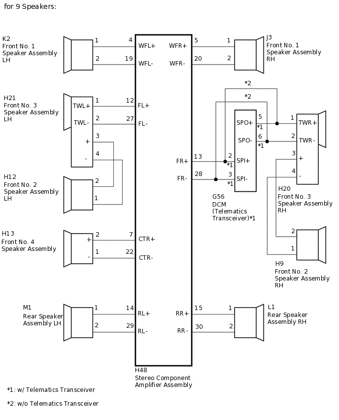
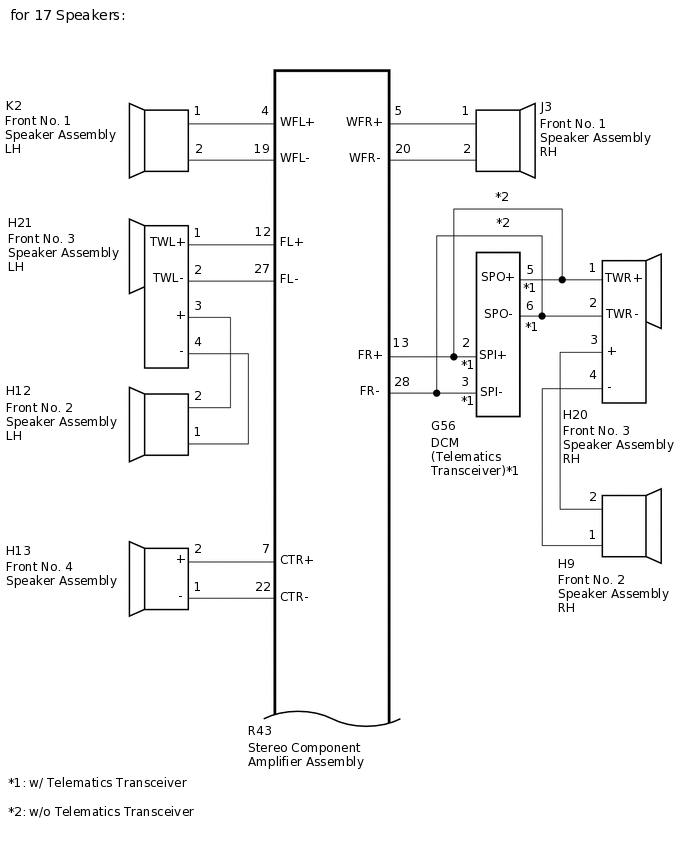
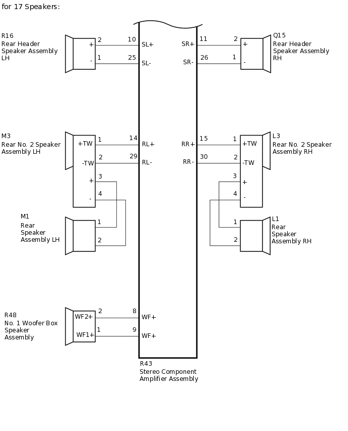
WIRING DIAGRAM
CAUTION / NOTICE / HINT
If the DCM (telematics transceiver) has been replaced, perform the DCM Activation procedure using the GTS (w/ Telematics Transceiver).
PROCEDURE
CLEAR DTC
Clear the DTCs.
Body Electrical > Navigation System > Clear DTCs
Result
Proceed
NEXT
CHECK FOR DTC
Recheck for DTCs and check if the same DTC is output again.
OK
DTC B15C3 is not output.
Body Electrical > Navigation System > Trouble Codes
Result
Proceed
OK
NG
CHECK HARNESS AND CONNECTOR
*1: for RH Side
*2: for LH Side
*3: w/ Telematics Transceiver
*4: w/o Telematics Transceiver
*5: for 9 Speakers
*6: for 17 Speakers
Disconnect the H48*5 and/or R43*6 stereo component amplifier assembly connector.
Disconnect the J3*1 and/or K2*2 front No. 1 speaker assembly connector.
Disconnect the H9*1 and/or H12*2 front No. 2 speaker assembly connector.
Disconnect the H20*1 and/or H21*2 front No. 3 speaker assembly connector.
Disconnect the H13 front No. 4 speaker assembly connector.
Disconnect the L1*1 and/or M1*2 rear speaker assembly connector.
Disconnect the L3*1 and/or M3*2 rear No. 2 speaker assembly connector*6.
Disconnect the Q15*1 and/or R16*2 rear header speaker assembly connector*6.
Disconnect the R48 No. 1 woofer box speaker connector*6.
Measure the resistance according to the value(s) in the table below.
Standard Resistance
for 9 Speakers (for RH Side)
Tester Connection
Condition
Specified Condition
H48-5 (WFR+) - J3-1
Always
Below 1 Ω
H48-20 (WFR-) - J3-2
Always
Below 1 Ω
H48-13 (FR+) - G56-2 (SPI+)*3
Always
Below 1 Ω
H48-28 (FR-) - G56-3 (SPI-)*3
Always
Below 1 Ω
H48-13 (FR+) - H20-1 (TWR+)*4
Always
Below 1 Ω
H48-28 (FR-) - H20-2 (TWR-)*4
Always
Below 1 Ω
G56-5 (SPO+) - H20-1 (TWR+)*3
Always
Below 1 Ω
G56-6 (SPO-) - H20-2 (TWR-)*3
Always
Below 1 Ω
H20-3 (+) - H9-2
Always
Below 1 Ω
H20-4 (-) - H9-1
Always
Below 1 Ω
H48-15 (RR+) - L1-1
Always
Below 1 Ω
H48-30 (RR-) - L1-2
Always
Below 1 Ω
H48-5 (WFR+) - Body ground
Always
10 kΩ or higher
H48-20 (WFR-) - Body ground
Always
10 kΩ or higher
H48-13 (FR+) - Body ground
Always
10 kΩ or higher
H48-28 (FR-) - Body ground
Always
10 kΩ or higher
G56-5 (SPO+) - Body ground*3
Always
10 kΩ or higher
G56-6 (SPO-) - Body ground*3
Always
10 kΩ or higher
H20-3 (+) - Body ground
Always
10 kΩ or higher
H20-4 (-) - Body ground
Always
10 kΩ or higher
H48-15 (RR+) - Body ground
Always
10 kΩ or higher
H48-30 (RR-) - Body ground
Always
10 kΩ or higher
Table 1. for 9 Speakers (for LH Side): Tester Connection
Condition
Specified Condition
H48-4 (WFL+) - K2-1
Always
Below 1 Ω
H48-19 (WFL-) - K2-2
Always
Below 1 Ω
H48-12 (FL+) - H21-1 (TWL+)
Always
Below 1 Ω
H48-27 (FL-) - H21-2 (TWL-)
Always
Below 1 Ω
H21-3 (+) - H12-2
Always
Below 1 Ω
H21-4 (-) - H12-1
Always
Below 1 Ω
H48-14 (RL+) - M1-1
Always
Below 1 Ω
H48-29 (RL-) - M1-2
Always
Below 1 Ω
H48-4 (WFL+) - Body ground
Always
10 kΩ or higher
H48-19 (WFL-) - Body ground
Always
10 kΩ or higher
H48-12 (FL+) - Body ground
Always
10 kΩ or higher
H48-27 (FL-) - Body ground
Always
10 kΩ or higher
H21-3 (+) - Body ground
Always
10 kΩ or higher
H21-4 (-) - Body ground
Always
10 kΩ or higher
H48-14 (RL+) - Body ground
Always
10 kΩ or higher
H48-29 (RL-) - Body ground
Always
10 kΩ or higher
Table 2. for 9 Speakers (for Center Side): Tester Connection
Condition
Specified Condition
H48-7 (CTR+) - H13-2 (+)
Always
Below 1 Ω
H48-22 (CTR-) - H13-1 (-)
Always
Below 1 Ω
H48-7 (CTR+) - Body ground
Always
10 kΩ or higher
H48-22 (CTR-) - Body ground
Always
10 kΩ or higher
Table 3. for 17 Speakers (for RH Side): Tester Connection
Condition
Specified Condition
R43-5 (WFR+) - J3-1
Always
Below 1 Ω
R43-20 (WFR-) - J3-2
Always
Below 1 Ω
R43-13 (FR+) - G56-2 (SPI+)*3
Always
Below 1 Ω
R43-28 (FR-) - G56-3 (SPI-)*3
Always
Below 1 Ω
G56-5 (SPO+) - H20-1 (TWR+)*3
Always
Below 1 Ω
G56-6 (SPO-) - H20-2 (TWR-)*3
Always
Below 1 Ω
R43-13 (FR+) - H20-1 (TWR+)*4
Always
Below 1 Ω
R43-28 (FR-) - H20-2 (TWR-)*4
Always
Below 1 Ω
H20-3 (+) - H9-2
Always
Below 1 Ω
H20-4 (-) - H9-1
Always
Below 1 Ω
R43-11 (SR+) - Q15-2 (+)
Always
Below 1 Ω
R43-26 (SR-) - Q15-1 (-)
Always
Below 1 Ω
R43-15 (RR+) - L3-1 (+TW)
Always
Below 1 Ω
R43-30 (RR-) - L3-2 (-TW)
Always
Below 1 Ω
L3-3 (+) - L1-1
Always
Below 1 Ω
L3-4 (-) - L1-2
Always
Below 1 Ω
R43-5 (WFR+) - Body ground
Always
10 kΩ or higher
R43-20 (WFR-) - Body ground
Always
10 kΩ or higher
R43-13 (FR+) - Body ground
Always
10 kΩ or higher
R43-28 (FR-) - Body ground
Always
10 kΩ or higher
G56-5 (SPO+) - Body ground*3
Always
10 kΩ or higher
G56-6 (SPO-) - Body ground*3
Always
10 kΩ or higher
H20-3 (+) - Body ground
Always
10 kΩ or higher
H20-4 (-) - Body ground
Always
10 kΩ or higher
R43-11 (SR+) - Body ground
Always
10 kΩ or higher
R43-26 (SR-) - Body ground
Always
10 kΩ or higher
R43-15 (RR+) - Body ground
Always
10 kΩ or higher
R43-30 (RR-) - Body ground
Always
10 kΩ or higher
L3-3 (+) - Body ground
Always
10 kΩ or higher
L3-4 (-) - Body ground
Always
10 kΩ or higher
Table 4. for 17 Speakers (for LH Side): Tester Connection
Condition
Specified Condition
R43-4 (WFL+) - K2-1
Always
Below 1 Ω
R43-19 (WFL-) - K2-2
Always
Below 1 Ω
R43-12 (FL+) - H21-1 (TWL+)
Always
Below 1 Ω
R43-27 (FL-) - H21-2 (TWL-)
Always
Below 1 Ω
H21-3 (+) - H12-2
Always
Below 1 Ω
H21-4 (-) - H12-1
Always
Below 1 Ω
R43-10 (SL+) - R16-2 (+)
Always
Below 1 Ω
R43-25 (SL-) - R16-1 (-)
Always
Below 1 Ω
R43-14 (RL+) - M3-1 (+TW)
Always
Below 1 Ω
R43-29 (RL-) - M3-2 (-TW)
Always
Below 1 Ω
M3-3 (+) - M1-1
Always
Below 1 Ω
M3-4 (-) - M1-2
Always
Below 1 Ω
R43-4 (WFL+) - Body ground
Always
10 kΩ or higher
R43-19 (WFL-) - Body ground
Always
10 kΩ or higher
R43-12 (FL+) - Body ground
Always
10 kΩ or higher
R43-27 (FL-) - Body ground
Always
10 kΩ or higher
H21-3 (+) - Body ground
Always
10 kΩ or higher
H21-4 (-) - Body ground
Always
10 kΩ or higher
R43-10 (SL+) - Body ground
Always
10 kΩ or higher
R43-25 (SL-) - Body ground
Always
10 kΩ or higher
R43-14 (RL+) - Body ground
Always
10 kΩ or higher
R43-29 (RL-) - Body ground
Always
10 kΩ or higher
M3-3 (+) - Body ground
Always
10 kΩ or higher
M3-4 (-) - Body ground
Always
10 kΩ or higher
Table 5. for 17 Speakers (for Center Side): Tester Connection
Condition
Specified Condition
R43-7 (CTR+) - H13-2 (+)
Always
Below 1 Ω
R43-22 (CTR-) - H13-1 (-)
Always
Below 1 Ω
R43-8 (WF+) - R48-2 (WF2+)
Always
Below 1 Ω
R43-9 (WF+) - R48-1 (WF1+)
Always
Below 1 Ω
R43-7 (CTR+) - Body ground
Always
10 kΩ or higher
R43-22 (CTR-) - Body ground
Always
10 kΩ or higher
R43-8 (WF+) - Body ground
Always
10 kΩ or higher
R43-9 (WF+) - Body ground
Always
10 kΩ or higher
Result
Proceed to
OK
NG
NG REPAIR OR REPLACE HARNESS OR CONNECTOR
INSPECT FRONT NO. 1 SPEAKER ASSEMBLY
Remove the front No. 1 speaker assembly.
Inspect the front No. 1 speaker assembly.
Result
Proceed to
OK
NG
INSPECT FRONT NO. 2 SPEAKER ASSEMBLY
Remove the front No. 2 speaker assembly.
Inspect the front No. 2 speaker assembly.
Result
Proceed to
OK
NG
CHECK FRONT NO. 3 SPEAKER ASSEMBLY
Replace the front No. 3 speaker assembly with a known good one.
Check for DTCs and check if the same DTC is output.
Body Electrical > Navigation System > Trouble Codes
OK
No DTCs are output.
Result
Proceed to
OK
NG (w/Telematics Transceiver)
NG (w/o Telematics Transceiver)
OK END (FRONT NO. 3 SPEAKER ASSEMBLY IS DEFECTIVE)
NG (w/o Telematics Transceiver) INSPECT FRONT NO. 4 SPEAKER ASSEMBLYClick here
INSPECT DCM (FRONT NO. 3 SPEAKER ASSEMBLY IS DEFECTIVE)
-
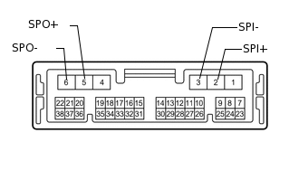
Remove the DCM (telematics transceiver).
Measure the resistance according to the value(s) in the table below.
Standard Resistance
Tester Connection
Condition
Specified Condition
2 (SPI+) - 5 (SPO+)
Always
Below 1 Ω
3 (SPI-) - 6 (SPO-)
Always
Below 1 Ω
2 (SPI+) - Body ground
Always
10 kΩ or higher
3 (SPI-) - Body ground
Always
10 kΩ or higher
Result
Proceed to
OK
NG
-
INSPECT FRONT NO. 4 SPEAKER ASSEMBLY
Remove the front No. 4 speaker assembly.
Inspect the front No. 4 speaker assembly.
Result
Result
OK
NG
INSPECT REAR SPEAKER ASSEMBLY
Remove the rear speaker assembly.
Inspect the rear speaker assembly.
Result
Proceed to
OK (for 17 Speakers)
OK (for 9 Speakers)
NG
INSPECT REAR NO. 2 SPEAKER ASSEMBLY
Remove the rear No. 2 speaker assembly.
Inspect the rear No. 2 speaker assembly.
Result
Proceed
OK
NG
INSPECT REAR HEADER SPEAKER ASSEMBLY
Remove the rear header assembly.
Inspect the rear header assembly.
Result
Proceed
OK
NG
INSPECT NO. 1 WOOFER BOX SPEAKER ASSEMBLY
Remove the No. 1 woofer box speaker assembly.
Inspect the No. 1 woofer box speaker assembly.
Result
Proceed
OK
NG