PARKING BRAKE ASSEMBLY REASSEMBLY
CAUTION / NOTICE / HINT
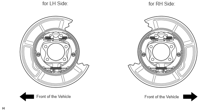
Use the same procedure for the RH and LH sides.
The procedure listed below is for the LH side.
PROCEDURE
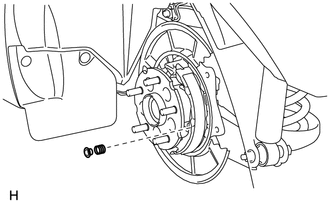
INSTALL NO. 1 PARKING BRAKE SHOE HOLD DOWN SPRING PIN
-
Install the No. 1 parking brake shoe hold down spring pin.
-
INSTALL NO. 2 PARKING BRAKE SHOE HOLD DOWN SPRING PIN
-
Install the No. 2 parking brake shoe hold down spring pin.
-
APPLY HIGH TEMPERATURE GREASE
-
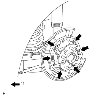
Apply high temperature grease to the areas of the backing plate that contact the shoe.
Table 1. Text in Illustration *1
High temperature grease
-
CONNECT NO. 3 PARKING BRAKE CABLE ASSEMBLY
-
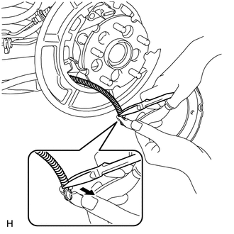
Using needle-nose pliers, connect the No. 3 parking brake cable assembly to the parking brake shoe lever as shown in the illustration.
Note:Be careful not to damage the No. 3 parking brake cable assembly.
-
INSTALL NO. 2 PARKING BRAKE SHOE ASSEMBLY
-
Install the No. 2 parking brake shoe, shoe hold down spring and shoe hold down spring cup.
-
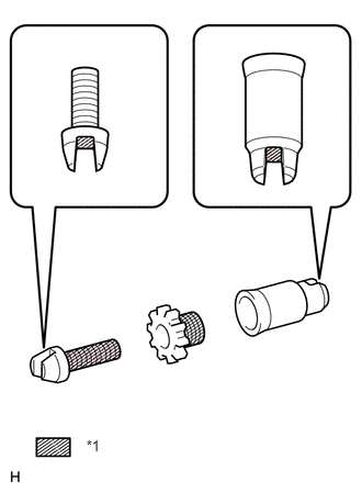
Apply high temperature grease to the threads and all contact surfaces of the parking brake shoe adjuster screw set.
Table 2. Text in Illustration *1
High temperature grease
-
Set the No. 2 parking brake shoe and shoe adjuster screw set in place.
-

Connect the tension spring.
-
INSTALL PARKING BRAKE SHOE STRUT
-
Install the parking brake shoe strut.
-
INSTALL NO. 1 PARKING BRAKE SHOE ASSEMBLY LH
-
Install the No. 1 parking brake shoe, shoe hold down spring and shoe hold down spring cup.
Install the tension spring to the No. 1 parking brake shoe.
-
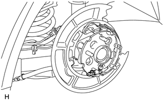
INSTALL PARKING BRAKE SHOE RETURN SPRING
-
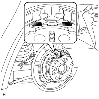
Install the 2 return springs.
Tip:First install the front side spring and then the rear side spring.
-
CHECK PARKING BRAKE INSTALLATION
Check that each part is installed properly.
 Note:
Note:There should be no oil or grease on the friction surfaces of the shoe lining and disc.
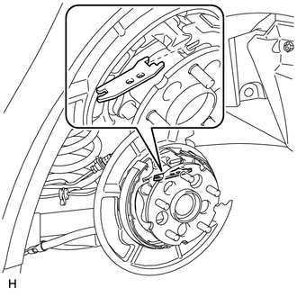
INSTALL REAR DISC
-
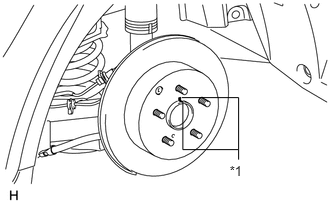
Align the matchmarks and install the rear disc.
Table 3. Text in Illustration *1
Matchmark
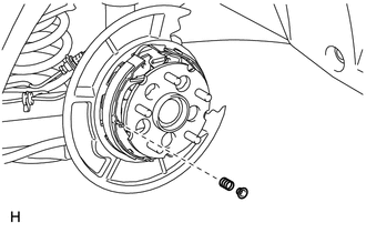
Install the shoe adjusting hole plug.
-
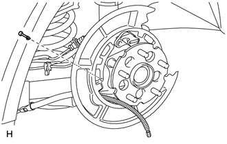
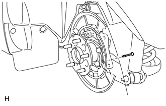
CONNECT REAR DISC BRAKE CYLINDER ASSEMBLY LH
-
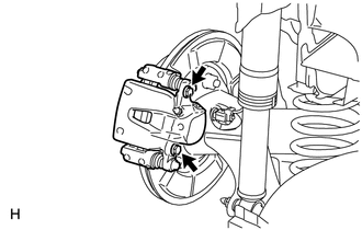
Connect the rear disc brake cylinder with the 2 bolts.
72 N*m
734 kgf*cm
53 ft.*lbf
Note:Do not twist the brake hose.
Make sure that the bolts are free from damage and foreign matter.
-
CHECK PARKING BRAKE LEVER TRAVEL
ADJUST PARKING BRAKE LEVER TRAVEL
INSTALL REAR WHEEL LH
103 N*m
1050 kgf*cm
76 ft.*lbf
SETTLE PARKING BRAKE SHOE AND DISC
Drive the vehicle for approximately 400 m (0.25 miles) under the following conditions.
The vehicle speed is approximately 50 km/h (31 mph) and the vehicle is on a safe, level and dry road.
The parking brake lever is being pulled with a force of 150 N (15 kgf, 33.7 lbf).
Repeat the procedure above 2 or 3 times.
Note:Set a 5-minute interval between each procedure to prevent the brake assembly from overheating.