TIRE PRESSURE WARNING SYSTEM TC and CG Terminal Circuit
| DTC Code | DTC Name |
|---|---|
| TC and CG Terminal Circuit |
DESCRIPTION
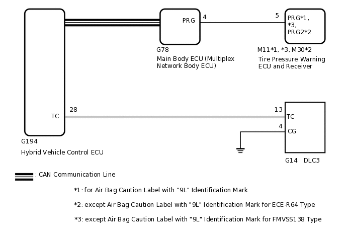
DTC output mode is set by connecting terminals 13 (TC) and 4 (CG) of the DLC3. The DTCs are indicated by the blinking of the tire pressure warning light.
WIRING DIAGRAM
PROCEDURE
CHECK CAN COMMUNICATION SYSTEM
Check the CAN communication system.
for LHD:Click hereClick here
for RHD:Click hereClick here
CAN Bus Check
OK
The CAN communication system is normal.
Result
Proceed to
OK
NG
CHECK DTC OUTPUT (C2179/79)
Clear the DTCs.
Chassis > Tire Pressure Monitor > Clear DTCs
Turn the power switch off.
Turn the power switch on (IG).
Check for DTCs.
Chassis > Tire Pressure Monitor > Trouble Codes
OK
DTC C2179/79 is not output.
Result
Proceed to
OK
NG
CHECK HARNESS AND CONNECTOR (TC of DLC3 - HYBRID VEHICLE CONTROL ECU)
Disconnect the hybrid vehicle control ECU G194 connector.
Measure the resistance according to the value(s) in the table below.
Standard Resistance
Tester Connection
Condition
Specified Condition
G14-13 (TC) - G194-28 (TC)
Always
Below 1 Ω
Result
Proceed to
OK
NG
NG REPAIR OR REPLACE HARNESS OR CONNECTOR
CHECK HARNESS AND CONNECTOR (CG of DLC3 - BODY GROUND)
-
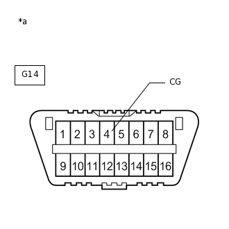
*a
Front view of DLC3
Measure the resistance according to the value(s) in the table below.
Standard Resistance
Tester Connection
Condition
Specified Condition
G14-4 (CG) - Body ground
Always
Below 1 Ω
Result
Proceed to
OK
NG
NG REPAIR OR REPLACE HARNESS OR CONNECTOR
-
INSPECT DLC3 (TC VOLTAGE)
Connect the hybrid vehicle control ECU G194 connector.
-

*a
Front view of DLC3
Measure the voltage according to the value(s) in the table below.
Standard Voltage
Tester Connection
Switch Condition
Specified Condition
G14-13 (TC) - G14-4 (CG)
Power switch on (IG)
11 to 14 V
Result
Proceed to
OK
NG