FUEL PUMP ECU REMOVAL
CAUTION / NOTICE / HINT
The necessary procedures (adjustment, calibration, initialization or registration) that must be performed after parts are removed and installed, or replaced during fuel pump control ECU removal/installation are shown below.
| Replaced Part or Performed Procedure | Necessary Procedure | Effect/Inoperative Function when Necessary Procedure not Performed | Link |
|---|---|---|---|
| Battery terminal is disconnected/reconnected | Perform steering sensor zero point calibration | Lane departure alert system (w/ Steering Control) | |
| Pre-collision system | |||
| Memorize steering angle neutral point | Parking assist monitor system |
CAUTION:
-
Wear protective gloves. Sharp areas on the parts may injure your hands.
-
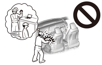
Some of these service operations affect the SRS airbag system. Read the precautionary notices concerning the SRS airbag system before servicing.
-
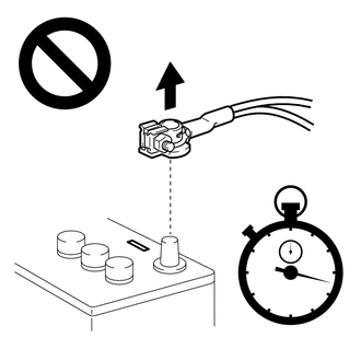
Wait at least 90 seconds after disconnecting the cable from the negative (-) battery terminal to disable the SRS system.
-
If an airbag deploys for any reason, it may cause a serious injury.
PROCEDURE
-
PRECAUTION
Note
After turning the engine switch off, waiting time may be required before disconnecting the cable from the negative (-) battery terminal. Therefore, make sure to read the disconnecting the cable from the negative (-) battery terminal notices before proceeding with work.
-
DISCONNECT CABLE FROM NEGATIVE BATTERY TERMINAL
Note
When disconnecting the cable, some systems need to be initialized after the cable is reconnected.
-
DISCONNECT REAR CENTER SEAT OUTER BELT ASSEMBLY
-
REMOVE REAR SEAT CUSHION ASSEMBLY
-
REMOVE REAR SEAT CUSHION LOCK HOOK
-
REMOVE REAR SEATBACK COVER
-
REMOVE REAR SEATBACK ASSEMBLY LH
-
DISCONNECT REAR DOOR OPENING TRIM WEATHERSTRIP LH
-
REMOVE REAR SIDE SEATBACK ASSEMBLY LH
-
DISCONNECT REAR DOOR OPENING TRIM WEATHERSTRIP RH
Tech Tips
Use the same procedure as for the LH side.
-
REMOVE REAR SIDE SEATBACK ASSEMBLY RH
Tech Tips
Use the same procedure as for the LH side.
-
REMOVE CENTER STOP LIGHT SET
-
DISCONNECT REAR SEAT OUTER BELT ASSEMBLY LH
-
DISCONNECT REAR SEAT OUTER BELT ASSEMBLY RH
Tech Tips
Use the same procedure as for the LH side.
-
REMOVE INNER ROOF SIDE GARNISH LH
-
REMOVE INNER ROOF SIDE GARNISH RH
Tech Tips
Use the same procedure as for the LH side.
-
REMOVE REAR SEAT SHOULDER BELT HOLE COVER
-
REMOVE PACKAGE TRAY TRIM PANEL ASSEMBLY (w/o Rear Sunshade)
-
REMOVE PACKAGE TRAY TRIM PANEL ASSEMBLY (w/ Rear Sunshade)
-
REMOVE ROOM PARTITION BOARD LH
-
REMOVE FUEL PUMP CONTROL ECU
-
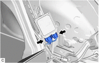
Disconnect the 2 fuel pump control ECU connectors.
-
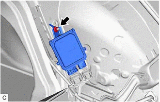
Remove the nut and fuel pump control ECU from the vehicle body.
Note
Do not reuse the fuel pump control ECU if it has been dropped or subjected to a severe impact.
-
-
REMOVE FUEL PUMP CONTROL ECU BRACKET
-
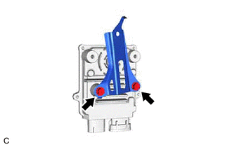
Remove the 2 bolts and fuel pump control ECU bracket from the fuel pump control ECU.
-