G-BOOK SYSTEM(w/ Telematics Transceiver) Emergency Call Switch Illumination Circuit
| DTC Code | DTC Name |
|---|---|
| Emergency Call Switch Illumination Circuit |
WIRING DIAGRAM
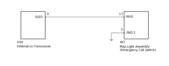
CAUTION / NOTICE / HINT
When replacing the telematics transceiver, perform the vehicle contract setting (Click here).
PROCEDURE
CHECK HARNESS AND CONNECTOR (TELEMATICS TRANSCEIVER - MAP LIGHT ASSEMBLY)
Disconnect the G56 telematics transceiver connector.
Disconnect the W7 map light assembly connector.
Measure the resistance according to the value(s) in the table below.
Standard Resistance
Tester Connection
Condition
Specified Condition
W7-17 (RRID) - G56-9 (SLED)
Always
Below 1 Ω
W7-17 (RRID) - Body ground
Always
10 kΩ or higher
W7-5 (GND3) - Body ground
Always
Below 1 Ω
Result
Result
OK
NG
NG REPAIR OR REPLACE HARNESS OR CONNECTOR
INSPECT MAP LIGHT ASSEMBLY
-
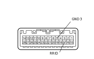
Remove the map light assembly.
Disconnect the W7 map light assembly connector.
Connect 4 1.5 V dry-cell batteries in series.
Connect the positive (+) lead from the batteries to terminal W7-17 (RRID), and the negative (-) lead to terminal W7-5 (GND3) of the map light assembly connector.
Check if the illumination for the emergency call switch comes on.
OK
Measurement Condition
Specified Condition
Battery positive (+) → W7-17 (RRID)
Illumination for the emergency call switch comes on
Battery negative (-) → W7-5 (GND3)
Result
Result
OK
NG
-