ANTI-LOCK BRAKE SYSTEM TERMINALS OF ECU
-
TERMINALS OF ECU
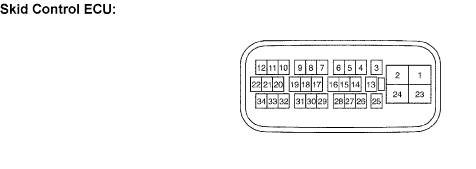
Symbols (Terminal No.) Terminal Description +BS (1) Power supply for solenoid GND1 (2) Skid control ECU ground P (6)* P shift position switch signal FL- (8) Front left wheel speed sensor output FL+ (9) Front left wheel speed sensor input STP (10) Stop light switch input RL+ (11) Rear left wheel speed sensor input RL- (12) Rear left wheel speed sensor output WA (13) ABS warning light output D/G (14) Diagnosis tester communication line TS (15) Sensor check switch input TC (16) Diagnosis switch input PKB (18) Parking brake switch input N (20)* N shift position switch signal +BM (23) Power supply for motor GND2 (24) Skid control ECU ground IG1 (25) ECU power supply FR- (30) Front right wheel speed sensor output FR+ (31) Front right wheel speed sensor input RR+ (33) Rear right wheel speed sensor input RR- (34) Rear right wheel speed sensor output
-
*: for Automatic Transmission
-
-
TERMINAL INSPECTION
-
Disconnect the connector and measure the voltage or resistance on the wire harness side.
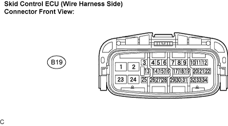
Tech Tips
Voltage cannot be measured with the connector connected to the skid control ECU as the connector is watertight.
Symbols (Terminal No.) Wiring Color Terminal Description Condition Specified Condition +BS (B19-1) - Body ground W-R - Body ground Power supply for solenoid (Front battery) Always 10 to 14 V GND1 (B19-2) - Body ground W-B - Body ground Skid control ECU ground Always Below 1 Ω STP (B19-10) - Body ground G - Body ground Stop light switch input Stop light switch ON → OFF (Brake pedal depressed → released) 8 to 16 V → Below 1.5 V PKB (B19-18) - Body ground B - Body ground Parking brake switch input Ignition switch ON, parking brake switch ON → OFF Below 1.5 V → 10 to 14 V +BM (B19-23) - Body ground W - Body ground Power supply for motor (Front battery) Always 10 to 14 V GND2 (B19-24) - Body ground W-B - Body ground Skid control ECU ground Always Below 1 Ω IG1 (B19-25) - Body ground B - Body ground ECU power supply Ignition switch off → ON Below 1 V → 10 to 14 V
-