WIPER AND WASHER SYSTEM(w/ Rain Sensor) Rain Sensor Circuit
| DTC Code | DTC Name |
|---|---|
| Rain Sensor Circuit |
DESCRIPTION
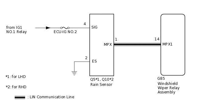
The windshield wiper relay assembly receives a signal from the rain sensor to control the auto wiper system.
WIRING DIAGRAM
CAUTION / NOTICE / HINT
Inspect the fuses for circuits related to this system before performing the following inspection procedure.
PROCEDURE
CHECK HARNESS AND CONNECTOR (WINDSHIELD WIPER RELAY ASSEMBLY - RAIN SENSOR)
Disconnect the G85 windshield wiper relay assembly connector.
Disconnect the Q5*1 or Q10*2 rain sensor connector.
*1: for LHD
*2: for RHD
Measure the resistance according to the value(s) in the table below.
Standard Resistance
Table 1. for LHD Tester Connection
Condition
Specified Condition
G85-14 (MPX1) - Q5-1 (MPX)
Always
Below 1 Ω
G85-14 (MPX1) - Body ground
Always
10 kΩ or higher
Table 2. for RHD Tester Connection
Condition
Specified Condition
G85-14 (MPX1) - Q10-1 (MPX)
Always
Below 1 Ω
G85-14 (MPX1) - Body ground
Always
10 kΩ or higher
Result
Proceed to
OK
NG
NG REPAIR OR REPLACE HARNESS OR CONNECTOR
CHECK HARNESS AND CONNECTOR (RAIN SENSOR - BATTERY AND BODY GROUND)
-
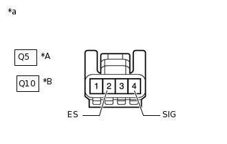
*A
for LHD
*B
for RHD
*a
Front view of wire harness connector
(to Rain Sensor)
Disconnect the rain sensor connector.
Measure the resistance according to the value(s) in the table below.
Standard Resistance
Table 3. for LHD Tester Connection
Condition
Specified Condition
Q5-2 (ES) - Body ground
Always
Below 1 Ω
Table 4. for RHD Tester Connection
Condition
Specified Condition
O10-2 (ES) - Body ground
Always
Below 1 Ω
Measure the voltage according to the value(s) in the table below.
Standard Voltage
Table 5. for LHD Tester Connection
Switch Condition
Specified Condition
Q5-4 (SIG) - Body ground
Ignition switch ON
11 to 14 V
Ignition switch off
Below 1 V
Table 6. for RHD Tester Connection
Switch Condition
Specified Condition
Q10-4 (SIG) - Body ground
Ignition switch ON
11 to 14 V
Ignition switch off
Below 1 V
Result
Proceed to
OK
NG
NG REPAIR OR REPLACE HARNESS OR CONNECTOR
-
CHECK RAIN SENSOR
-
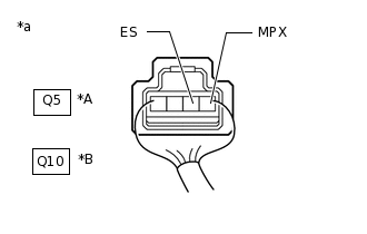
*A
for LHD
*B
for RHD
*a
Component with harness connected
(Rain Sensor)
Remove the rain sensor with the connector(s) still connected.
Connect an oscilloscope to terminals 1 (MPX) and 2 (ES) of the rain sensor connector.
Check the waveform of the rain sensor using the oscilloscope.
OK
Table 7. for LHD Tester Connection
Switch Condition
Specified Condition
O5-1 (MPX) - O5-2 (ES)
Ignition switch ON
Pulse generation
Table 8. for RHD Tester Connection
Switch Condition
Specified Condition
O10-1 (MPX) - O10-2 (ES)
Ignition switch ON
Pulse generation
Result
Proceed to
OK
NG
-