UPPER INSTRUMENT PANEL REMOVAL
CAUTION / NOTICE / HINT
Use the same procedure for RHD and LHD vehicles.
The procedure listed below is for LHD vehicles.
PROCEDURE
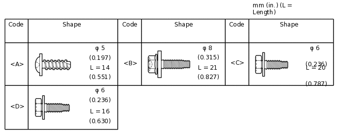
TABLE OF BOLT, SCREW AND NUT
Tip:All bolts, screws and nuts relevant to installing and removing the instrument panel are shown along with their alphabet code in the table below.
PRECAUTION
Note:After turning the ignition switch off, waiting time may be required before disconnecting the cable from the battery terminal. Therefore, make sure to read the disconnecting the cable from the battery terminal notice before proceeding with work.
DISCONNECT CABLE FROM NEGATIVE BATTERY TERMINAL
CAUTION:Wait at least 90 seconds after disconnecting the cable from the negative (-) battery terminal to disable the SRS system.
Note:When disconnecting the cable, some systems need to be initialized after the cable is reconnected.
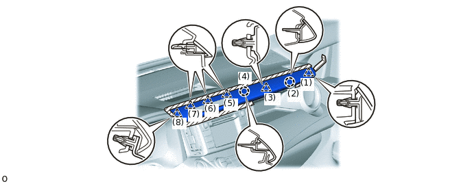
REMOVE CENTER NO. 1 INSTRUMENT CLUSTER FINISH PANEL
Apply protective tape as shown in the illustration.
Using moulding remover B, detach the 6 clips and 2 claws in the order shown in the illustration and remove the center No. 1 instrument cluster finish panel.

Protective Tape
-
-
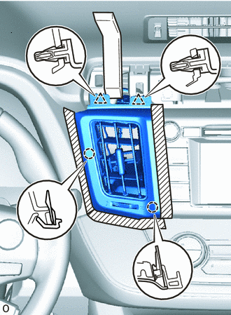
REMOVE NO. 3 INSTRUMENT PANEL REGISTER ASSEMBLY
-
Protective Tape
Apply protective tape as shown in the illustration.
Using moulding remover B, detach the 2 clips and 2 claws and remove the No. 3 instrument panel register assembly.
-
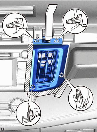
REMOVE NO. 4 INSTRUMENT PANEL REGISTER ASSEMBLY
-
Protective Tape
Apply protective tape as shown in the illustration.
Using moulding remover B, detach the 3 clips and claw and remove the No. 4 instrument panel register assembly.
-
REMOVE TELLTALE LIGHT ASSEMBLY
REMOVE STEREO OPENING COVER (w/o Audio)
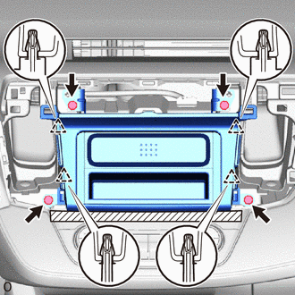
Protective Tape
Apply protective tape as shown in the illustration.
Remove the 4 bolts.
Detach the 4 clips and remove the stereo opening cover.
REMOVE RADIO RECEIVER ASSEMBLY (w/ Audio, for Radio Receiver Type)
REMOVE RADIO AND DISPLAY RECEIVER ASSEMBLY (w/ Audio, for Radio and Display Type)
REMOVE NAVIGATION RECEIVER (w/ Navigation System)
REMOVE NO. 1 INSTRUMENT CLUSTER FINISH PANEL
Protective Tape
Apply protective tape as shown in the illustration.
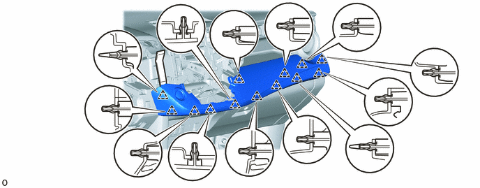
Using moulding remover B, detach the claw and 11 clips and remove the No. 1 instrument cluster finish panel.
REMOVE COMBINATION METER ASSEMBLY
REMOVE HEADLIGHT DIMMER SWITCH
REMOVE LOWER CENTER INSTRUMENT CLUSTER FINISH PANEL SUB-ASSEMBLY (except Automatic Air Conditioning System)
Protective Tape
Apply protective tape as shown in the illustration.
Detach the 2 clips and remove the lower center instrument cluster finish panel sub-assembly.
Disconnect each connector.
REMOVE AIR CONDITIONING CONTROL ASSEMBLY (for Automatic Air Conditioning System)
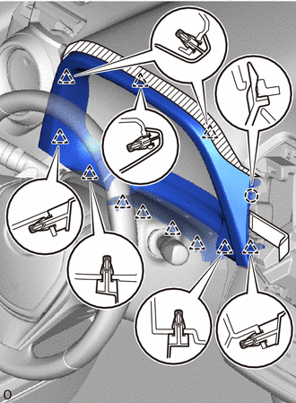
REMOVE NO. 2 INSTRUMENT PANEL GARNISH SUB-ASSEMBLY
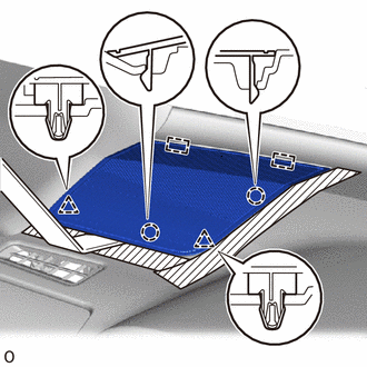
Using moulding remover B, detach the 13 clips and remove the No. 2 instrument panel garnish sub-assembly.
-
for LHD with Entry and Start System:
Disconnect the connector.
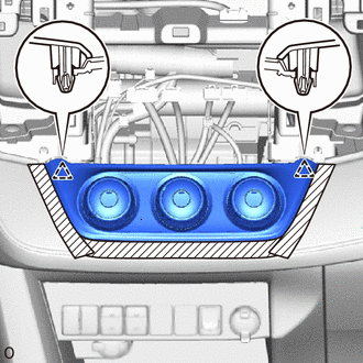
REMOVE UPPER INSTRUMENT CLUSTER FINISH PANEL
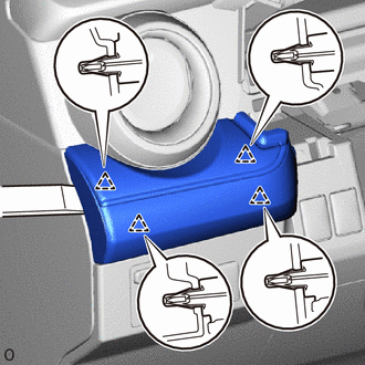
Using moulding remover B, detach the 4 clips and remove the upper instrument cluster finish panel.
REMOVE GLOVE COMPARTMENT DOOR ASSEMBLY
-
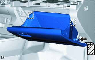
Protective Tape
Apply protective tape as shown in the illustration.
Disconnect the glove compartment door stopper sub-assembly.
Slightly bend the upper part of the glove compartment door assembly to release the 2 stoppers and open the glove compartment door assembly until it is horizontal.
-
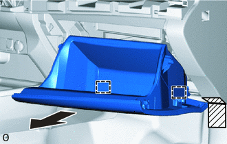
Protective Tape
Pull the glove compartment door assembly toward the rear of the vehicle to detach the 2 hinges and remove it.
-
REMOVE NO. 2 SPEAKER HOLE COVER (w/o Speaker)
Protective Tape
Apply protective tape as shown in the illustration.
Using moulding remover B, detach the 2 clips, 2 claws and 2 guides and remove the No. 2 speaker hole cover.
REMOVE NO. 1 SPEAKER HOLE COVER (w/o Speaker)
Tip:Use the same procedure described for the No. 2 speaker hole cover.
REMOVE NO. 2 SPEAKER HOLE COVER (w/ Speaker)
REMOVE NO. 1 SPEAKER HOLE COVER (w/ Speaker)
Tip:Use the same procedure described for the No. 2 speaker hole cover.
REMOVE FRONT NO. 2 SPEAKER ASSEMBLY (w/ Speaker)
REMOVE FRONT PILLAR GARNISH LH (w/o Curtain Shield Airbag)
REMOVE FRONT PILLAR GARNISH RH (w/o Curtain Shield Airbag)
REMOVE FRONT PILLAR GARNISH LH (w/ Curtain Shield Airbag)
REMOVE FRONT PILLAR GARNISH RH (w/ Curtain Shield Airbag)
REMOVE UPPER INSTRUMENT PANEL
-
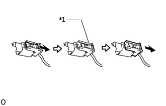
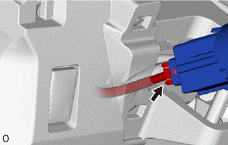
*1
Lock Slider

Pull
for Single Type Airbag:
Pull and slide the lock slider in the direction indicated by the arrow to release the connector lock and disconnect the airbag connector.
Note:When handling the airbag connector, take care not to damage the airbag wire harness.
Disconnect each connector.
Remove the 2 bolts <B>.
Remove the 2 bolts <C> or <D>.
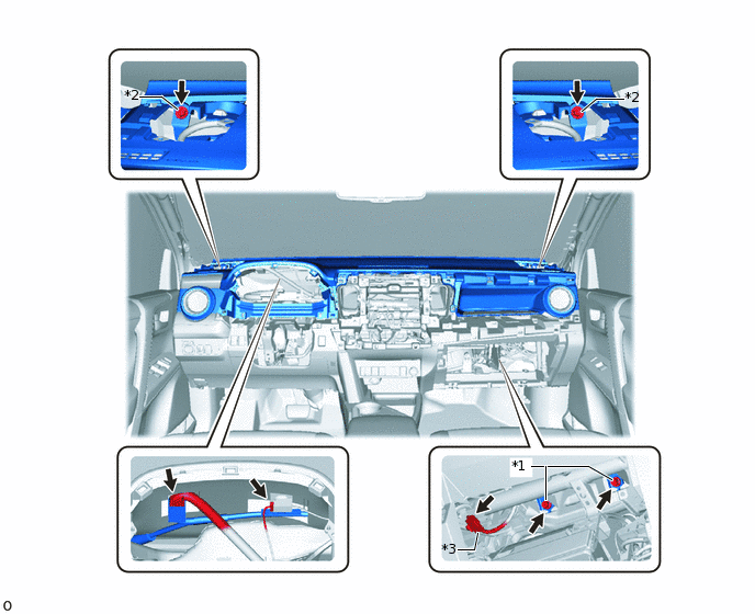
*1
Bolt <B>
*2
Bolt <C> or <D>
*3
Airbag Connector
-
-
-
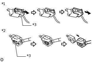
*1
Airbag Connector A
*2
Airbag Connector B
*3
Lock Slider
Pull
for Dual Type Airbag:
Pull and slide the lock slider in the direction indicated by the arrow to release the connector lock and disconnect the 2 airbag connectors A and B.
Note:When handling the airbag connector, take care not to damage the airbag wire harness.
Disconnect each connector.
Remove the 2 bolts <B>.
Remove the 2 bolts <C> or <D>.
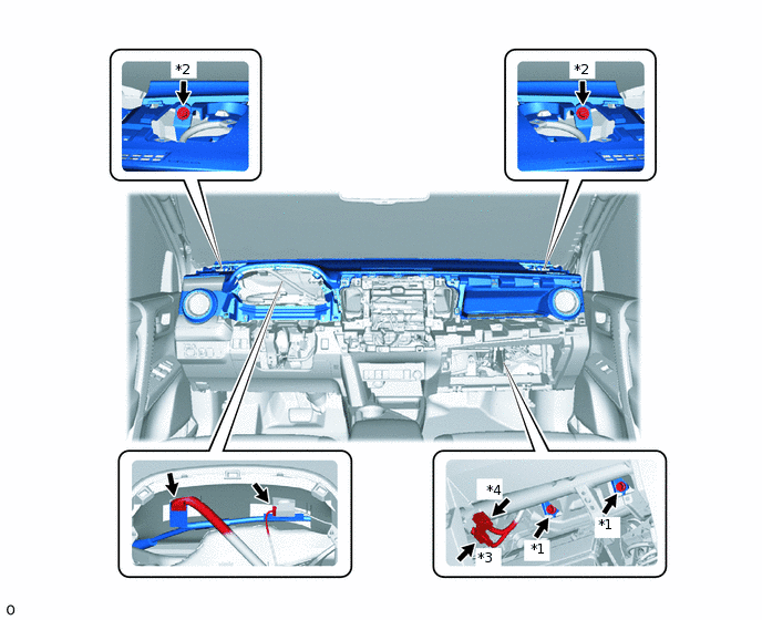
*1
Bolt <B>
*2
Bolt <C> or <D>
*3
Airbag Connector A
*4
Airbag Connector B
Pull up the upper instrument panel to detach the 8 clips and remove it.
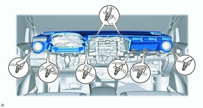
-