РАСПРЕДВАЛ УСТАНОВКА

CAUTION / NOTICE / HINT
CAUTION:
-
To prevent burns, do not touch the engine, exhaust manifold or other high temperature components while the engine is hot.
PROCEDURE
-
INSTALL NO. 2 CAMSHAFT BEARING
-
INSTALL NO. 1 CAMSHAFT BEARING
-
INSPECT CAMSHAFT TIMING GEAR ASSEMBLY
-
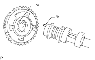
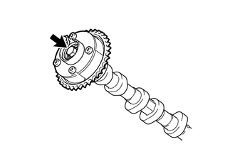
*a Knock Pin Hole *b Knock Pin Align and fit the knock pin of the camshaft to the knock pin hole of the camshaft timing gear assembly.
-
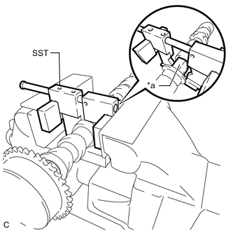
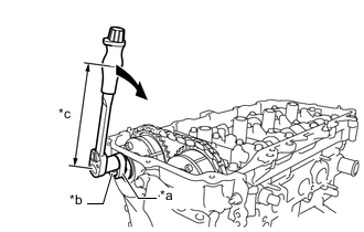
*a Hexagonal Portion Using SST, grip the hexagonal portion, and then secure the SST and camshaft in a vise as shown in the illustration and check that the camshaft timing gear assembly does not rotate.
- SST
- 09212-31010
Note
-
Do not damage the camshaft.
-
Never grip areas other than the hexagonal portion, as this may cause damage.
-
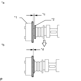
*1 Camshaft Timing Gear Assembly *2 Camshaft Flange *a Incorrect *b Correct *c Gap *d No Gap Check that there is no gap between the camshaft timing gear assembly and camshaft flange.
-
While securely holding the camshaft, install the bolt of the camshaft timing gear assembly by hand.
- Torque:
- 85 N*m { 867 kgf*cm, 63 ft.*lbf }
Note
Do not use any tools to install the bolt. If the bolt is installed using a tool, the lock pin will be damaged.
-
Check the lock of the camshaft timing gear assembly.
-
Make sure that the camshaft timing gear assembly is locked.
Note
Be careful not to damage the camshaft.
-
-
Release the lock pin.
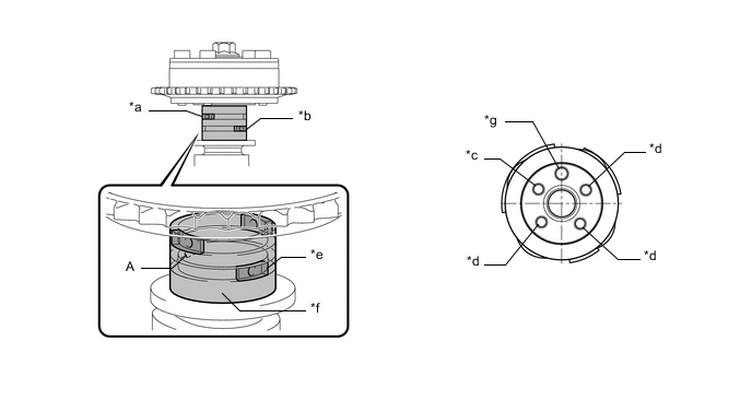
*a Retard Side Path *b Advance Side Path *c Open *d Close *e Rubber Piece *f Vinyl Tape *g Knock Pin - -
-
Clean the camshaft journal with non-residue solvent.
-
Cover the 4 oil paths of the cam journal with vinyl tape as shown in the illustration.
Tech Tips
There are 4 oil paths in the grooves of the camshaft. Plug 3 of the oil paths with rubber pieces.
-
Make a hole in the tape over the port (A) shown in the illustration.
-
While applying approximately 200 kPa (2.0 kgf/cm2, 29 psi) of air pressure to the oil path, forcibly turn the camshaft timing gear assembly in the advance direction (counterclockwise).
CAUTION:
Cover the oil paths with a piece of cloth when applying air pressure to prevent oil from spraying.
Note
Do not allow the camshaft timing gear assembly to lock. If it locks, release the lock pin again.
Tech Tips
-
Depending on the air pressure applied, the camshaft timing gear assembly may turn in the advance direction without assistance by hand.
-
If enough air pressure cannot be applied because of air leakage from the port, releasing the lock pin may be difficult.
-
-
-
Check for smooth rotation.
-
Turn the camshaft timing gear assembly within its movable range (26.5 to 28.5°) 2 or 3 times, but do not turn it to the most retarded position. Make sure that the camshaft timing gear assembly turns smoothly.
Note
-
Do not use air pressure to perform the smooth operation check.
-
Do not allow the camshaft timing gear assembly to lock. If it locks, release the lock pin again.
-
-
-
Remove the vinyl tape and rubber pieces from the camshaft.
-
Remove the bolt and camshaft timing gear assembly.
-
-
INSTALL OIL CONTROL VALVE FILTER
-
INSTALL CAMSHAFT TIMING EXHAUST GEAR ASSEMBLY
-
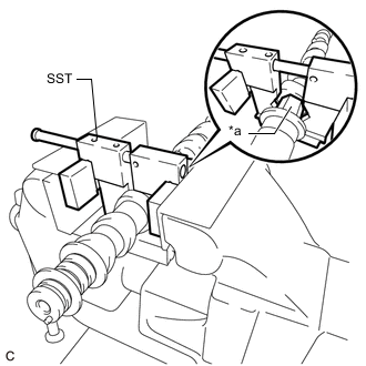
*a Hexagonal Portion Using SST, grip the hexagonal portion, and then secure the SST and No. 2 camshaft in a vise as shown in the illustration.
- SST
- 09212-31010
Note
-
Do not damage the No. 2 camshaft.
-
Never grip areas other than the hexagonal portion, as this may cause damage.
-
Install the camshaft timing exhaust gear assembly to the No. 2 camshaft with the bolt.
- Torque:
- 85 N*m { 867 kgf*cm, 63 ft.*lbf }
-
-
SET NO. 1 CYLINDER TO TDC/COMPRESSION
-
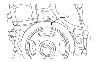
*a Timing Notch (Groove) Turn the crankshaft pulley until its timing notch (groove) and the timing mark "0" of the timing chain cover sub-assembly are aligned.
-
-
INSTALL NO. 2 CAMSHAFT
-

*1 No. 1 Valve Rocker Arm Sub-assembly *2 Valve Lash Adjuster Assembly *3 Valve Stem Cap Make sure that the No. 1 valve rocker arm sub-assemblies are installed as shown in the illustration.
-
Clean the camshaft journals.
-
Apply a light coat of engine oil to the camshaft journals, camshaft housing sub-assembly and camshaft bearing caps.
-
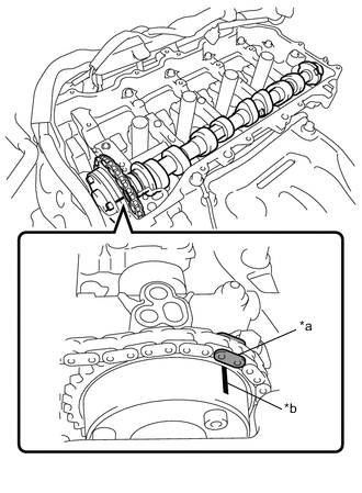
*a Paint Mark *b Timing mark Hold up the chain sub-assembly, align the timing mark and paint mark, and install the No. 2 camshaft to the camshaft housing sub-assembly.
-
-
INSTALL CAMSHAFT
-
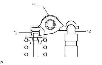
*1 No. 1 Valve Rocker Arm Sub-assembly *2 Valve Lash Adjuster Assembly *3 Valve Stem Cap Make sure that the No. 1 valve rocker arm sub-assemblies are installed as shown in the illustration.
-
Clean the camshaft journals.
-
Apply a light coat of engine oil to the camshaft journals, camshaft housing sub-assembly and camshaft bearing caps.
-
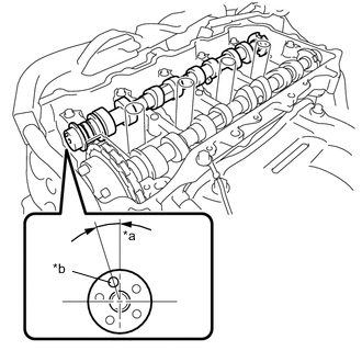
*a Approximately 17° *b Knock Pin Install the camshaft to the camshaft housing sub-assembly as shown in the illustration.
-
-
INSTALL CAMSHAFT BEARING CAP
-
Confirm the marks and numbers on the No. 2 camshaft bearing cap and 3 No. 3 camshaft bearing caps and place them and the No. 1 camshaft bearing cap in their proper positions and directions.
-
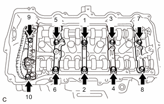
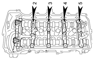
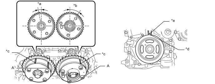
Uniformly tighten the 10 bolts in several steps in the order shown in the illustration.
- Torque:
- 27 N*m { 275 kgf*cm, 20 ft.*lbf }
-
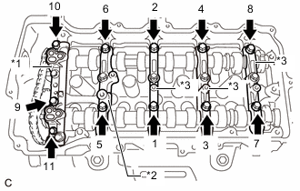
*1 No. 1 Camshaft Bearing Cap *2 No. 2 Camshaft Bearing Cap *3 No. 3 Camshaft Bearing Cap Uniformly tighten the 11 bolts in several steps in the order shown in the illustration.
- Torque:
- 16 N*m { 163 kgf*cm, 12 ft.*lbf }
-
Check the torque of each bolt again.
-
-
INSTALL CAMSHAFT TIMING GEAR ASSEMBLY
-
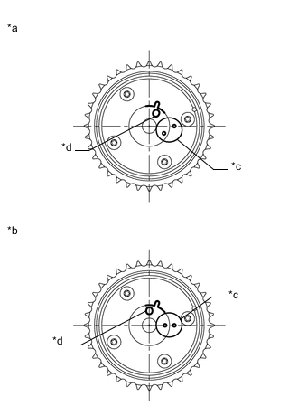
*a Advanced Position *b Retarded Position *c Alignment Mark *d Knock Pin Hole Check the camshaft timing gear assembly position.
Note
-
If the camshaft timing gear assembly is set to the advanced position, do not let the camshaft timing gear assembly rotate clockwise during installation.
-
If the camshaft timing gear assembly has rotated to the most retarded position, make sure to release the lock pin and set the camshaft timing gear assembly to the most advanced position before tightening the bolt of the camshaft timing gear assembly.
-
-
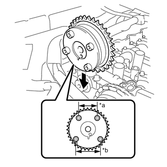
*a Narrow *b Wide Install the camshaft timing gear assembly as shown in the illustration.
-
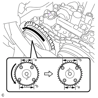
*a Narrow *b Wide Turn the camshaft timing gear assembly approximately 180° counterclockwise.
-
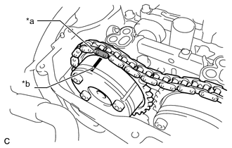
*a Paint Mark *b Timing Mark Align the paint mark with the timing mark and install the chain sub-assembly to the camshaft timing gear assembly.
-

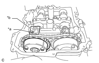
*a Knock Pin Hole *b Knock Pin Align and fit the knock pin of the camshaft to the knock pin hole of the camshaft timing gear assembly.
-

*1 Camshaft Timing Gear Assembly *2 Camshaft Flange *a Incorrect *b Correct *c Gap *d No Gap Check that there is no gap between the camshaft timing gear assembly and camshaft flange.
-
While securely holding the camshaft, install the bolt of the camshaft timing gear assembly by hand.
Note
Do not use any tools to install the bolt. If the bolt is installed using a tool, the lock pin will be damaged.
-
If the lock pin has not been released, release it.
-
*a Make a hole *b Adhesive Tape Sealing Area After cleaning the intake side VVT oil hole of the No. 1 camshaft bearing cap, completely seal the oil hole with adhesive tape or equivalent as shown in the illustration to prevent air from leaking.
Note
Be sure to seal the oil hole completely because air leaks due to insufficient sealing will prevent the lock pin from being released.
-
Make a hole in the adhesive tape as shown in the illustration.
-
Apply approximately 200 kPa (2.0 kgf/cm2, 29 psi) of air pressure to the open hole to release the lock pin.
Note
-
If air leaks out, reattach the adhesive tape.
-
Cover the hole with a piece of cloth when applying air pressure to prevent oil from spraying.
-
-
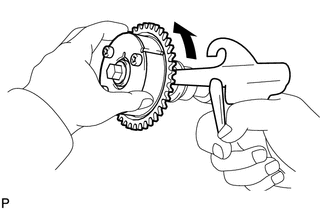
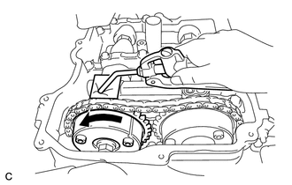
Forcibly turn the camshaft timing gear assembly in the advance direction (counterclockwise).
Tech Tips
-
Depending on the air pressure applied, the camshaft timing gear assembly may turn in the advance direction without assistance by hand.
-
If enough air pressure cannot be applied because of air leakage from the port, releasing the lock pin may be difficult.
-
-
Remove the adhesive tape from the No. 1 camshaft bearing cap.
-
-
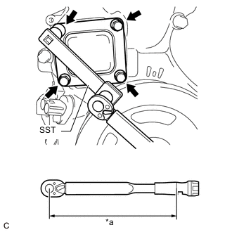
Using a wrench, hold the hexagonal portion of the camshaft.
-
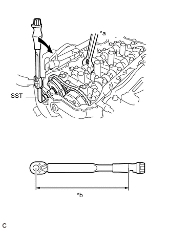
*a Hold *b Torque Wrench Fulcrum Length 
Turn Using SST, install the bolt.
- SST
- 09961-00950
- Torque:
- Specified Tightening Torque
- 85 N*m { 867 kgf*cm, 63 ft.*lbf }
Note
-
Be careful not to damage the camshaft housing sub-assembly, cylinder head sub-assembly or spark plug tube with the wrench.
-
Calculate the torque wrench reading when changing the fulcrum length of the torque wrench.
-
When using SST (fulcrum length of 150 mm (5.91 in.)) + torque wrench (fulcrum length of 255 mm (10.2 in.)): 53.5 N*m (546 kgf*cm, 39 ft.*lbf)
-
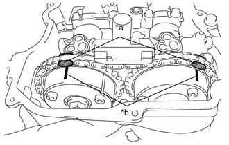
*a Paint Mark *b Timing Mark Check that the timing marks on the camshaft timing gear sub-assembly and camshaft timing exhaust gear assembly are facing upward as shown in the illustration.
Tech Tips
Perform "Inspection After Repair" after replacing the camshaft timing gear assembly.
-
-
ADD ENGINE OIL
-
INSTALL TIMING CHAIN GUIDE
-
INSTALL NO. 1 CHAIN TENSIONER ASSEMBLY
-
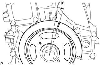
Turn the crankshaft pulley approximately 10° clockwise.
-
Install a new gasket and the No. 1 chain tensioner assembly with the 2 bolts.
- Torque:
- 10 N*m { 102 kgf*cm, 7 ft.*lbf }
Note
Be careful not to drop the gasket inside the timing chain cover sub-assembly.
-
Remove the pin from the stopper plate.
-
-
SET NO. 1 CYLINDER TO TDC/COMPRESSION
-
Turn the crankshaft pulley until its timing notch (groove) and the timing mark "0" of the timing chain cover sub-assembly are aligned.
*a Approximately 7° *b Approximately 32° *c Timing Mark *d Timing Notch (Groove) *e Timing Mark "0°" - - -
Check that the timing marks on the camshaft timing gear assembly and camshaft timing exhaust gear assembly are facing upward as shown in the illustration. If not, turn the crankshaft 1 revolution (360°) to align the timing marks as shown in the illustration.
Tech Tips
"A" is not a timing mark.
-
-
INSTALL TIMING CHAIN COVER PLATE
-
*a Torque Wrench Fulcrum Length Using SST, install a new gasket and the timing chain cover plate with the 4 bolts.
- SST
- 09961-00950
- Torque:
- Specified Tightening Torque
- 10 N*m { 102 kgf*cm, 7 ft.*lbf }
Note
-
Calculate the torque wrench reading when changing the fulcrum length of the torque wrench.
-
When using SST (fulcrum length of 150 mm (5.91 in.)) + torque wrench (fulcrum length of 162 mm (6.38 in.)): 5.2 N*m (53 kgf*cm, 46 ft.*lbf)
-
-
INSTALL OIL PUMP RELIEF VALVE PLUG
-
*a 14 mm Union Nut Wrench *b 14 mm Straight Hexagon Wrench *c Torque Wrench Fulcrum Length Turn Using a 14 mm straight hexagon wrench and 14 mm union nut wrench, install a new gasket and oil pump relief valve plug.
- Torque:
- Specified Tightening Torque
- 37.5 N*m { 382 kgf*cm, 28 ft.*lbf }
Note
-
Calculate the torque wrench reading when changing the fulcrum length of the torque wrench.
-
When using 14 mm union nut wrench (fulcrum length of 30 mm (1.18 in.)) + torque wrench (fulcrum length of 180 mm (7.09 in.)): 32.1 N*m (327 kgf*cm, 24 ft.*lbf)
-
-
INSTALL CYLINDER HEAD COVER SUB-ASSEMBLY
-
INSTALL IGNITION COIL ASSEMBLY
-
CONNECT ENGINE WIRE
-
Connect the engine wire to the engine assembly with the 3 bolts and 4 nuts.
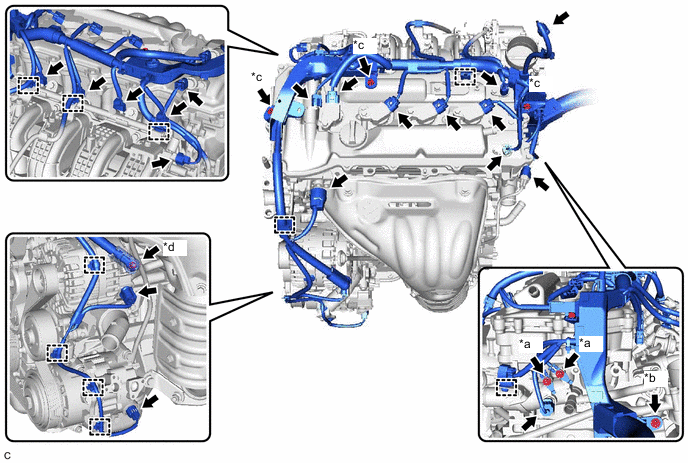
*a Bolt (A) *b Bolt (B) *c Nut (A) *d Nut (B) - Torque:
- Bolt (A)
- 8.4 N*m { 86 kgf*cm, 74 in.*lbf }
- Bolt (B) and Nut (A)
- 7.7 N*m { 79 kgf*cm, 68 in.*lbf }
- Nut (B)
- 9.8 N*m { 100 kgf*cm, 87 in.*lbf }
-
Connect the 17 connectors and 10 clamps.
-
-
INSTALL AIR CONDITIONER TUBE ASSEMBLY
-
Install the clamp, and connect the air conditioner tube assembly with the nut.
- Torque:
- 9.8 N*m { 100 kgf*cm, 87 in.*lbf }
-
-
INSTALL AIR CLEANER CASE SUB-ASSEMBLY
-
INSTALL AIR CLEANER CAP SUB-ASSEMBLY
-
INSTALL RADIATOR RESERVE TANK BRACKET
-
INSTALL RADIATOR RESERVE TANK ASSEMBLY
-
CONNECT CABLE TO NEGATIVE BATTERY TERMINAL
-
Connect the negative (-) battery terminal.
- Torque:
- 5.4 N*m { 55 kgf*cm, 48 in.*lbf }
Note
When disconnecting the cable, some systems need to be initialized after the cable is reconnected.
-
-
INSTALL OUTER COWL TOP PANEL SUB-ASSEMBLY
-
INSTALL REAR ENGINE UNDER COVER RH
-
INSPECT FOR ENGINE OIL LEAK
-
INSTALL FRONT WHEEL RH